Twister assembly manual
Step 0: Purchasing parts
Make sure you have all the items listed in the Parts, tools, and supplies page.
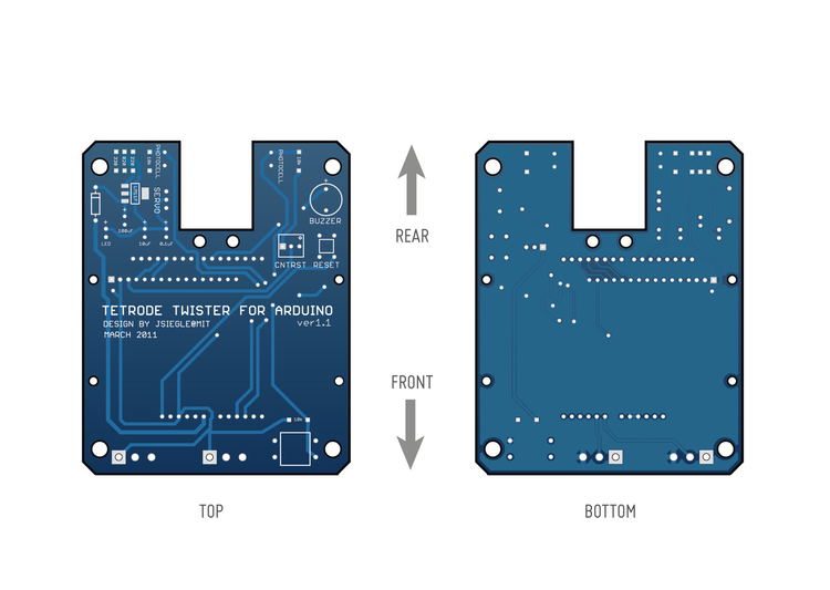
Step 1: Prepare the circuit board
Secure the circuit board in a vise. The side without lettering (bottom) should be facing up.
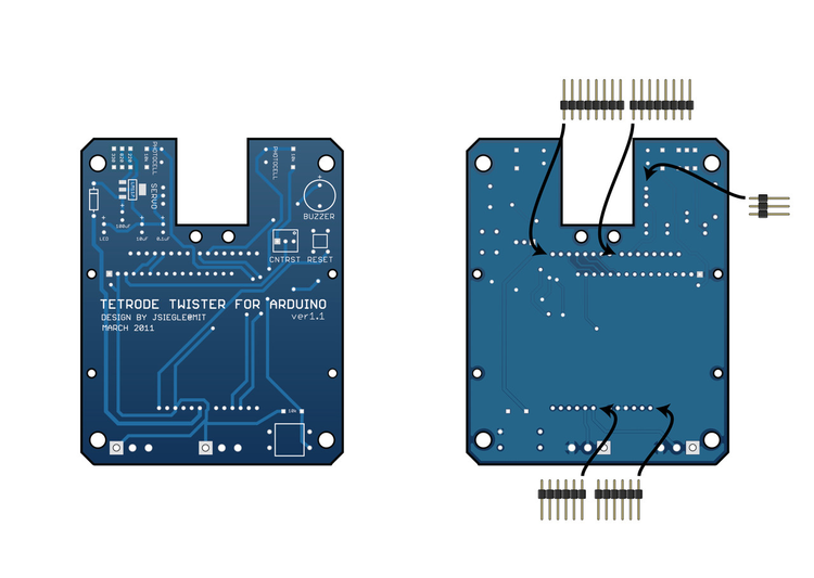
Step 2: Add bottom headers
Place the short ends of the 3, 6, and 8-segment headers through the bottom of the board. Use a piece of tape to secure them. Flip the board over and solder the headers in place.
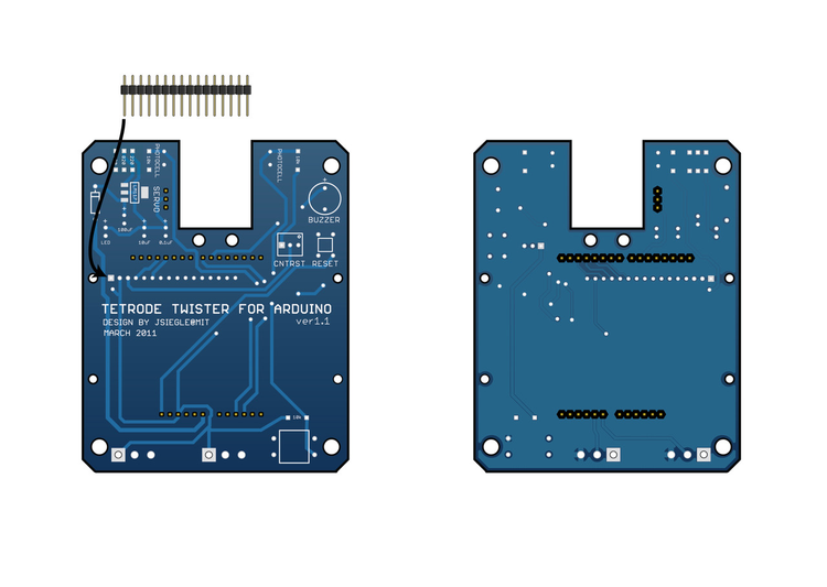
Step 3: Add top-side headers
With the top side facing up, place the long ends of the 16-segment header through the top of the board and secure with a piece of tape. Flip the board over and solder these headers from the bottom.
Step 4: Add LM1117
Place the LM1117 voltage regulator on the circuit board and solder it into place. Make sure there is solder connecting all four leads to their respective pads.

Step 5: Add resistors
Place the resistors on the top of the board and solder from the bottom. Suggested resistor values are approximate, and they can be changed if necessary. If you're using different values for the resistors labeled "220" and "820," use an LM317 calculator (http://www.electronics-lab.com/articles/LM317) to find a pair of resistors that will output ~6V.

Step 6: Add capacitors
Place the capacitors in the bottom of the board and solder from the top. If the capacitors are not placed on the bottom of the board, they will interfere with the case. Make sure the 10 µF and 100 µF caps have the longer lead in the "plus" hole. The 0.1 µF capacitors can be oriented in either direction.

Step 7: Add diodes
Place the diode rectifier and green LED on the top of the board and solder from the bottom. The longer lead of the LED goes into the "plus" hole. The stripe on the diode should be oriented as indicated on the circuit board.

Step 8: Add photocells
Place the photocells through the top of the board and solder from the bottom. The direction of the leads doesn't matter.

Step 9: Add buzzer
Place the buzzer through the top of the board and solder from the bottom. Make sure the plug signs on the board and buzzer are aligned.
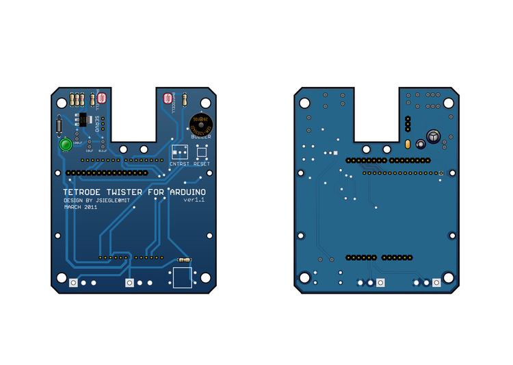
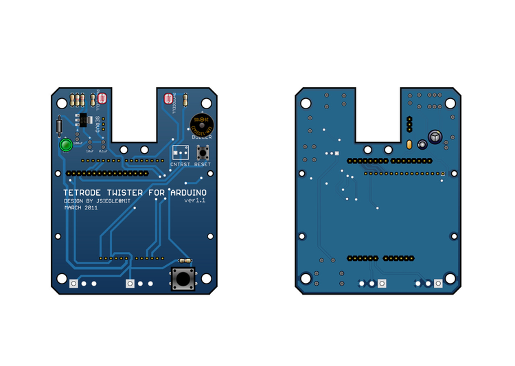
Step 10: Add buttons
Place the large and small buttons through the top of the board and solder from the bottom.
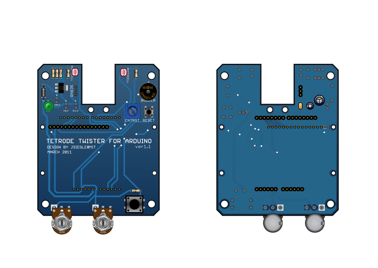
Step 11: Add potentiometers
Place one small potentiometer and two large potentiometers in the top of the board and solder from the bottom. The numbers on the small potentiometer should be on the opposite side of the holes from the "CNTRST" label.
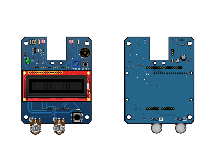
Step 12: Add display
Place the display over the 16-segment header and solder into place.
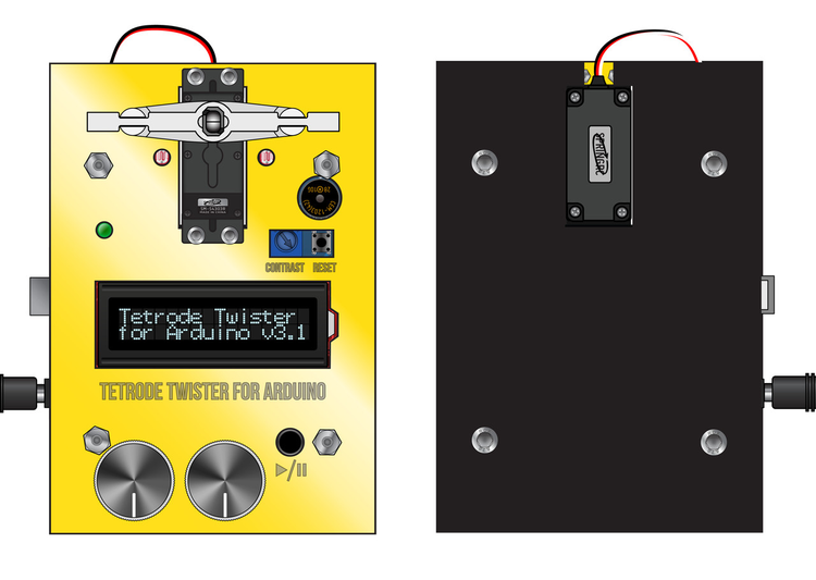
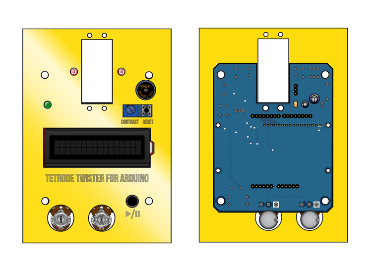
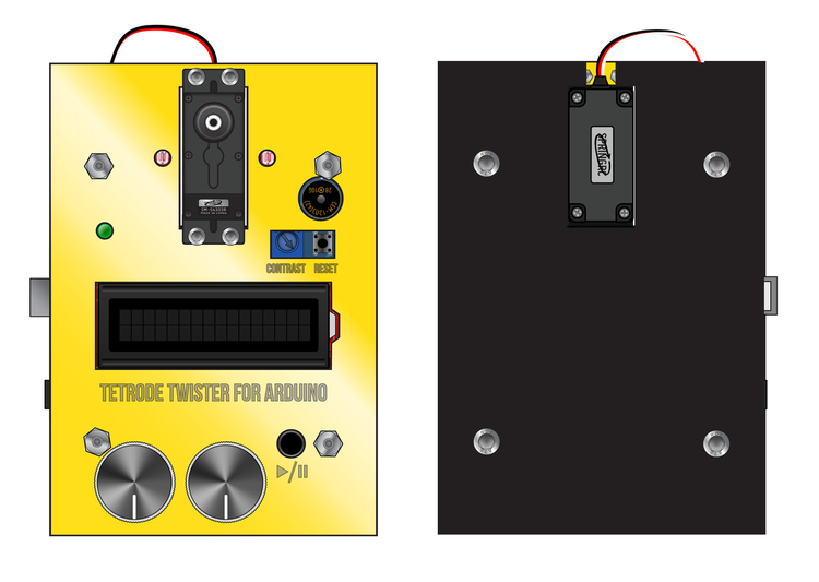
Step 13: Add the cover
Place the Twister cover over the assembly.
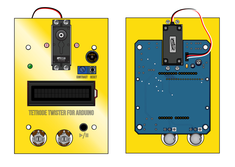
Step 14: Add the servo motor
Using for M3 screws and four M3 nuts, secure the servo to the cover and circuit board. Plug the servo into the appropriate headers, with the black wire toward the rear of the assembly.
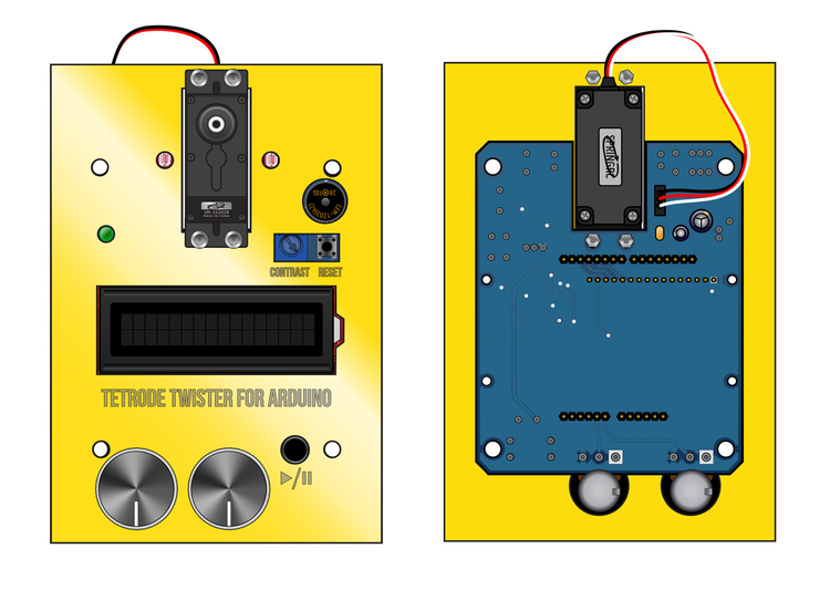
Step 15: Add knobs
Twist the large potentiometers as far to the left (counterclockwise) as possible. Place the black knobs on top of the large potentiometers with the white indicators facing toward the front. Use a vice to press the knobs firmly into place.
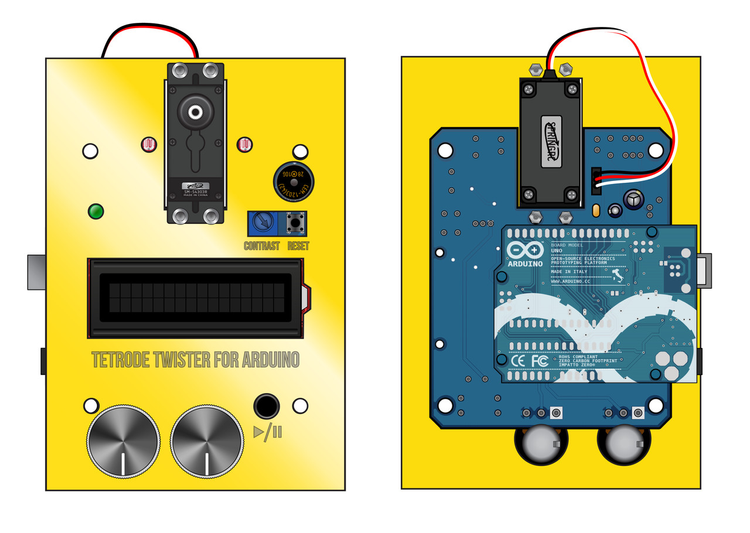
Step 16: Add Arduino board
Align the Arduino with the headers on the bottom of the board and press it into place. Do not apply any solder.
Step 17: Add the base
Place four M5 screws through the holes in the Twister base, four 25 mm M5 standoffs, and the holes in the cover. Secure the base with four M5 nuts.
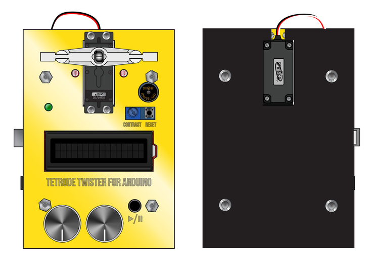
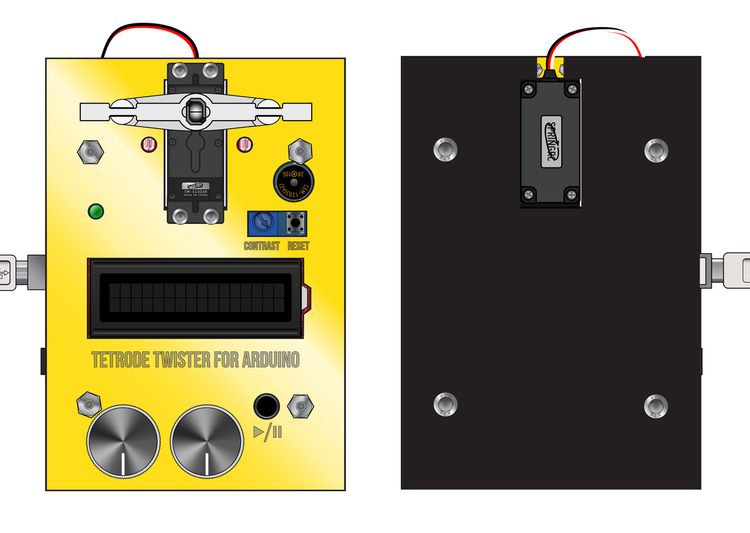
Step 18: Add the tetrode clip holder
Attach the tetrode clip to the clip holder with dental acrylic or epoxy. Attach the servo adapter to the linear servo arm with tape or glue. Press the adapter firmly onto the top of the servo motor.
Step 19: Upload firmware
Connect the Arduino to your computer via USB port. Upload the tetrode twister firmware using the Arduino IDE (available at http://arduino.cc)
Step 20: Attach power cable
Plug the Arduino board into a power outlet using the 9V power supply. You are now ready to twist!
Use the knobs to adjust the number of turns and the play/pause button to start and stop the twister.