This page has been moved to: https://open-ephys.github.io/acq-board-docs/User-Manual/Peripheral-devices.html#ioboard
If you just need one or two channels in a hurry, you can make a quick adapter cable with pretty little effort.
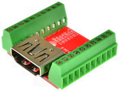
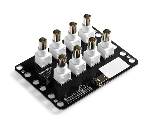
There are also a variety of simple HDMI breakout boards available from various vendors - these work equivalently as i/o boards. See for instance here.
HMDI channel mapping
| CH# | HDMI channel |
|---|---|
| 1 | DATA2+ |
| 2 | DATA2– |
| 3 | DATA1+ |
| 4 | DATA1– |
| 5 | DATA0+ |
| 6 | DATA0– |
| 7 | CLOCK+ |
| 8 | CLOCK– |
Testing cables and I/O modules
The easiest test is to check continuity and absence of shorts with a multimeter, using two I/O breakout boards and a hdmi cable. Alternatively, the same test can be performed with a acquisition board by plugging the hdmi cable into the Ain port and testing ontinuity between the bnc connectors and the row of 3-pin jumpers on the aq. board.
Displaying TTL/Analog inputs in the GUI
TTL/Din signals are displayed as shaded regions in the LFP display module, this display can be enabled/disabled individually for each of the 8 Digital input channels.
Analog inputs are always samples at the same rate and time as the neural signals and are displayed as additional channels in the LFP module, keep in mind that the input range for these signals is different form the neural signals and can be set separately.