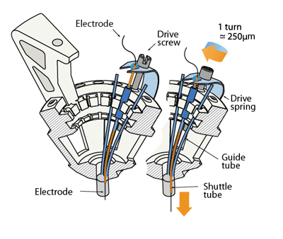
(The picture shows the shuttle tube extending almost all the way through the guide tube - this can increase the friction of the drive and cause problems. It is often better to keep the shuttle tubes as short as possible, so they stop short of the bend in the guide tube when the drive is fully lowered.)
Drive body assembly
In this step, the electrode guide tube array and the spring are attached to the drive body.
Next, individual guide tubes and arms of the spring are assembled into the drive mechanisms.
...
Depending on the quality of the 3d-print, finish the screw holes with #77 drill. Be careful to drill out the holes at the correct angle - with lower quality prints it is pretty easy to break through the inner wall of the drive body rim. Fitting a #77 drill bit into an ordinary electric drill might be a challenge. A keyless chuck (MCM Part #: 22-16500, Dremel Part #: 4486) can fit on a Dremel rotary tool, and holds even the finest drill bits.
Alternatively, the drill bit can be hold with a mini pin vise (MSC direct), than in turn will fit into an electric drill. It is worthwhile to test which drilling speed works best for each user - in some cases a higher speed tool such as a dremel can significantly simplify the drilling.
The slots along the inside perimter of the drive body may have to be finished with a #77 drill or razor blade if the print quality is low–they must be large enough to allow the 33ga polyimide tubing through.
Clean off plastic dust with compressed air, water, or ethanol, be careful when using ethanol as it will weaken the plastic when exposed for too long.
...
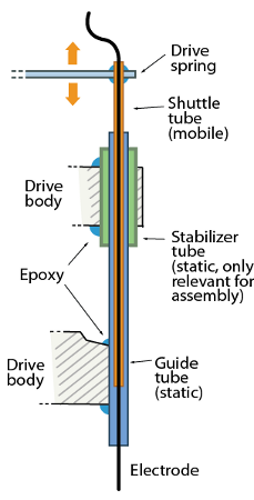
Glue guide tubes into place with thin layer of epoxy. It's okay if you get epoxy in between the guide tube and stabilizer tube.
(The picture shows the shuttle tube extending almost all the way through the guide tube - this can increase the friction of the drive and cause problems. It is often better to keep the shuttle tubes as short as possible, so they stop short of the bend in the guide tube when the drive is fully lowered.)
(optional) Map out the relationship between guide tubes at the drive bottom and the recently-glued guide tubes at the top of the drive by inserting a thin wire or spare tetrode into the guide tubes one at a time.
...