...
Here is a link to a fully filled-out digikey cart. It includes 5-10% extra of the very cheap (<$1) components, but otherwise no more than necessary for a single board.
 Opal Kelly - You'll need to buy one XEM6310 FPGA to install after the circuit board is assembled.
Case materials - The case consists of a 3D-printed box, a piece of laser-cut acrylic, four screws, and four rubber feet. Information on these components is available here: https://github.com/open-ephys/acquisition-board/tree/master/case
Cables - One 5V power supply, a USB 3.0 cable, and one or more thin, passive HDMI cables (type A to type A) for connecting to the I/O board.
I/O board (optional) - In order to connect to the analog or digital inputs, you'll need at least one I/O board. These can be purchased from the Open Ephys store, or assembled yourself.
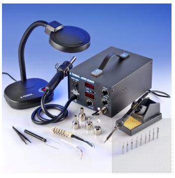
Hot air station - This is necessary only if you're building the board yourself. If you don't have one already, the X-TRONIC Model #4040 is a great deal for only $140. We've used it to make multiple acquisition boards and it works superbly!
...
If you're going to build the board yourself, you'll need to order a stencil and some solder paste. We recommend OSH Stencils, which are designed for small-run fabrications and are priced accordingly. You'll need to upload the same gerber.zip file that you used to print the PCB. Then identify the top solder paste file (*.tsp) as the top stencil and the board outline file (*.oln) as the board outline. Mark all other files, including all solder mask files, as unused. You don't need a bottom stencil because none of the components attach to the bottom of the board. The total cost should be about $21, with an option to buy a "jig" (which helps to position the stencil) for an additional $5. For the solder paste, do yourself a favor and buy SPE-0012 ZephPaste. It's by far the best solder paste we've used. Just remember to keep it refrigerated!
Step
...
4: Build the board
If you're outsourcing the assembly process, you'll need to supply Advanced Circuits with BOM.csv, centroid_file.csv, and fabrication_drawing.pdf. They'll take care of the rest, once they receive the components mentioned above.
...
- As a sanity check, use a multimeter to ensure none of the ground and power pins are connected (you can use the labels that are silkscreened onto the board). It's possible that this could occur as a result of the soldering process, and you want to be sure it's not a problem with the board itself.
- Secure the PCBs to a flat surface.
- Place the stencil on top of the PCB so the holes are aligned with the surface-mount pads.
- Put some solder paste at one end of the stencil, and use a thin sheet of metal (like a razor blade) to drag it across the holes. If you've never worked with surface-mount soldering before, we recommend watching YouTube videos and practicing a bit before you attempt this step. Capacitor C1 is a good one to practice on because it's pretty far from most of the other components.
- Now the fun begins! Place the components in the appropriate configuration, using the silkscreen labels, the acquisition-board.brd Eagle file, and centroid_file.csv as guides. Most components can be placed in any orientation. However, the diodes, and capacitors C22 and C59 must be placed in the orientation indicated on the board. All of the integrated circuits must be placed correctly, with pin 1 in the position marked by the circle on the silkscreen. If you're unsure about how it should look, you can use acquisition-board-populated.png as a reference. Plan on spending 3-4 hours on this step.
- Fire up that heat gun! Remove the nozzle (so the airflow is as wide as possible), then set the temperature to 300º C and the airflow to between 2 and 3. Once it heats up, place the tip about 2-3 cm from the board to heat up the solder. It may take a minute or two for the solder paste to start flowing. But once it does, things start to happen very quickly. As the solder paste melts, it will drag the components into place. Once this happens, move the nozzle to a nearby location, and repeat until the entire board has been soldered.
- Now it's time to troubleshoot. First, check the ground and power pins. If they're connected now, you have a problem. Check each of the SMD pins by eye to look for shorts. If they exist, they're usually easy to spot. If you find one, use a traditional soldering iron to divide the connection. Alternatively, you can use a straight scalpel blade to divide shorts. To do this, first use the heat gun to melt the solder, and then draw the solder blade in between the bridged legs. Because the scalpel blade is stainless steel, the solder will not stick to it. The most common locations for shorts between power and ground are underneath the small decoupling capacitors and underneath the components that have adjacent power and ground pins, such as the voltage regulators and the Adafruit LEDs.
- Assuming you don't have any power-to-ground connections, it's safe to plug in the power cord into the barrel jack on the board. ONLY USE A 5V DC POWER SUPPLY. Once the cord is plugged in, you can check the voltage levels using the holes on the bottom of the board. See the "How it works" page for more details, but most of the voltages should be within 0.1V of the specified level, except that +5va should be about 5.5V. Also, note that the 3.3V level is provided by the FPGA, so this voltage won't be set until the FPGA is plugged in.
Next, add jumpers to the 3-pin headers near the ADC input HDMI (DigiKey part #A26228-ND). We've chosen the ±5V input range as the default by bridging the two pins closest to the edge of the board).
- The final step is to put a drop of epoxy on either side of each Omnetics connector (be careful not the get glue on the pins) in order to keep them stable over many round of plugging/unplugging.
Step
...
5: Build the case
The shape of the case is specified by an STL (stereolithography) file called acquisition-board-case.stl (github). You can use it to have a case manufactured through a variety of methods, such as cast urethane (we recommend American Precision Prototyping), CNC machining (FirstCut), or 3D printing (Shapeways). Shapeways requires a .dae file, which is also included in the repository.
...