Prerequisites
This guide assume that you have an acquisition board with all the component soldered in place—either one that you built yourself, ordered from CircuitHub, or received from Open Ephys. If so, we'll walk you through the steps necessary to start collecting data with your board.
What you'll need
For each system that you want to use, you'll need the following:
1. One Opal Kelly XEM6010One Opal Kelly FPGA module (usually included with the acquisition board, but may also be purchased separately). We recommend using the XEM6310-LX45 ($499.95), which transmits data via USB 3.0, and supports up to 512 channels of simultaneous data acquisition. The board is also compatible with the Opal Kelly 6010-LX45 FPGA module ($399.95). This is what coordinates data acquisition and sends data to the computer via USB, which uses USB 2.0 and can handle up to 128 channels.
2. One or more headstages based on the Intan RHD2000-series amplifier chips. These are your options:
- RHD2132 amplifier/accelerometer board (recommended) - $995.00 (Intan Part #C3324)
- RHD2132 amplifier board - $895.00 (Intan Part #C3314)
- RHD2132 16-channel amplifier board - $705.00 (Intan Part #C3334)
- Open Ephys headstage - for information on how to build your own, see the discussion in the Headstages section.
3. At least one RHD2000 SPI interface cable per headstage. See further information on the Cables & Tethers page. These cables can be daisy-chained up to 10 meters. Any combination of the following will work:
- 3-foot SPI interface cable - $215.00 (Intan Part #C3203)
- 6-foot SPI interface cable - $295.00 (Intan Part #C3206)
- Cooner wire SPI interface cable - to build it yourself, follow the instructions in this blog post and here.
4. Various components (shown with price and recommended DigiKey part numbers)
- One heatsink ($2.43, #294-1097-ND)
- One thin, passive HDMI cable (type A to type A) (perhaps something like Q398-ND)
- 3 x 3 x 1 cm computer fan (optional)
- One Type A to Type B USB cable ($1.86, #Q361-ND, included from Opal Kelly)
- One 5V/6W power supply ($9.69, #SWI6-5-N-P5R )
- Eight through-hole vertical BNC connectors per I/O board ($2.73 each, #A97564-ND)
- One surface-mount HDMI connector per I/O board ($0.73, #609-4614-1-ND cut tape)
5. General lab supplies:
- Soldering iron (the thinner the better)
- Solder and flux
- 5-minute Epoxy (such as Z-poxy)
- M3 hex key (we like part #5984A42 from McMaster-Carr)
6. A reasonably fast modern computer (desktop or laptop) running Windows, Mac, or Linux.
- A solid-state hard drive is recommended if you need to record >32 channel simultaneously
- If you're using a laptop, make sure the acquisition board is grounded to a wall outlet (or your experiment ground). See the recording noise page.
Step 1: Installing the FPGA
NOTE: If your board already has an FPGA, you can skip this step.
Required components: Opal Kelly XEM6010-LX45, heatsink
Tools: M3 hex key or Phillips screwdriver, depending on your specific board
1. Flip the acquisition board over and use the hex key to remove the four screws. Some squeaking is to be expected.
...
2. Carefully remove the circuit board from the case by lifting the BNC and sliding it out.
3. Flip the circuit board face-up and place it on a flat surface.
4. Remove the backing from the heatsink and press it onto the main chip of the FPGA.
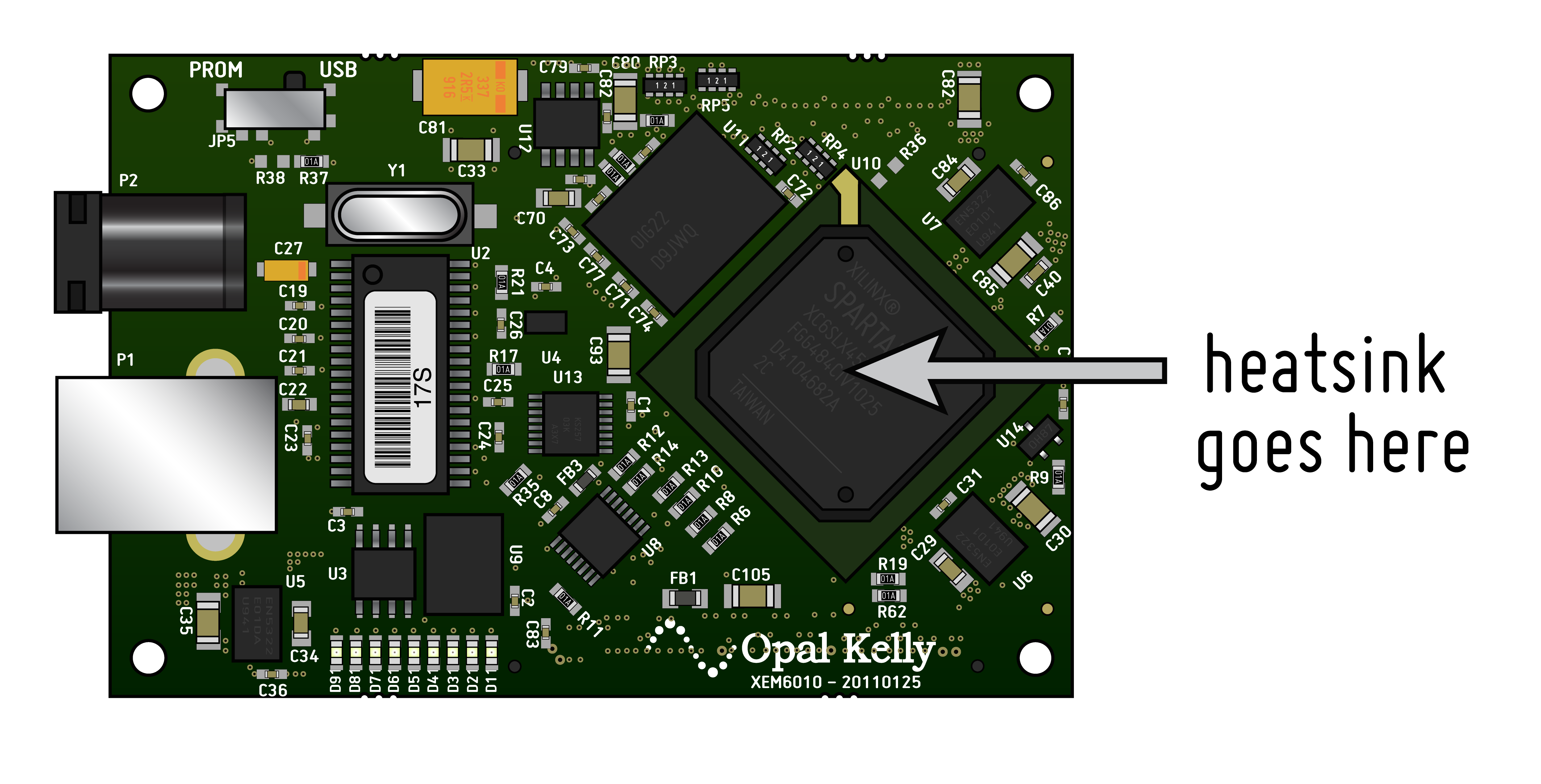
5. Align the connectors on the bottom of the FPGA with the connectors on the circuit board, and press the FPGA firmly into place.
...
5b. (optional) insert a 3x3x1cm fan into the opening in the case, and connect the fan power cable to the 3-pin fan connector on the acquisition board (polarity doesn't matter). Fold the cable up so it doesnt loop around the case too much. If the fan is scratching the side of the case, just rotate it 180 degrees, the air flow should be sufficient in either direction.
6. Place the circuit board back into the case, and replace the four screws. To insert the board, first carefully slide the four small headstage connectors through their opening in the case, hold the board at an angle for this step. The HDMI connectors should now easily fit into their openings. Dont force the board in at this stage, if there's too much resistance, the alignment is likely wrong and you risk bending the pins on the omnetics connectors. Once the front edge is in the housing, just push the board in using the front as a hinge. The Opal Kelly board should easily fit into the four guide posts in the case now.
Step 2: Connecting the USB and power supply
Required components: USB cable, 5V power supply
This one's pretty straightforward, but there are a few things to keep in mind:
- IMPORTANT: make sure you're using a 5V DC power supply! Other types of power supplies will permanently damage the board.
- Use the power jack on the FPGA , not the one on the acquisition board. The acquisition board power jack is only necessary if you're transmitting data via PCI express.
- USB cables longer than 2 meters are not recommended.
Step 3: Connecting the headstages
Required components: RHD2132 headstage, SPI cables
There are four headstage connectors on the front of the acquisition board. You can use any combination of the four (but you might as well start with input "A"). The connectors on the SPI cables are very small, so sometimes they can be tricky to insert. Make sure everything is properly aligned before you apply pressure, otherwise you might break the connector. Plug the opposite end of each cable (or series of daisy-chained cables) into a headstage.
Step 4: Connecting peripheral devices
External devices that generate digital or analog signals can interface with Open Ephys system through an I/O board. We're using HDMI cables to connect to the I/O board, as these are cheap and have exactly the right number of shielded wires inside of them.
To build your own I/O board, follow the instructions here.
If you're in a hurry, you can splice together a BNC and (passive!) HDMI cable to make a one-channel I/O cable. See here for instructions.
Once your I/O board(s) or HDMI cables are ready, the HDMI connections on the acquisition board are as follows (from left to right):
...
 | ±5V analog output |
 | ±5V analog input |
 | 0/5V digital output |
 | 0/5V digital input |
Step 5: Operation
The software interface is covered in the documentation for the Rhythm FPGA module, but there a few things to know about the hardware itself.
Using it with a laptop
If you're using the acquisition board with a laptop that's running off battery power, you will have a "floating" ground. This will cause your signals to look extremely noisy. To fix the issue, connect the ground of the acquisition board to whatever ground you're using for your experimental setup (perhaps a wall socket or a Faraday cage). You can either do this via the BNC connector (alligator clips work well for this), or by attaching a wire to one of the two dedicated screw terminals on the side of the board. The screw terminals are preferred because someday we may do something with the BNC. If you use the BNC, ground the shell of it to the wall, not the center pin. Connecting center pin of the BNC to ground will short your board and may fry the FPGA.
ADC input range
The default setting is to have the ADCs run from -5 to +5V, although in practice the actual range is ±4.5V (up through Acquisition Board version 2.2). If you need to go up to 5V, the ADC must be switched to 0-5V mode.
To switch the ADC range, open up the case and move the jumpers near the ADC input HDMI to the two pins farther away from the edge of the board. Different channels can have different jumper settings, but make sure you record which is which! There's no way for the software to know the setting for each channel. Channel 1 is the rightmost jumper (closer to the headstage inputs), Channel 8 is the leftmost jumper.
There is also a small DC offset (~0.4 V) on the ADCs when they're in ±5V range. This offset is taken into account by the Open Ephys GUI, but since the offset can be slightly different for each channel, the traces may not be exactly centered around zero. Be sure to measure the "zero" value for each channel if you're doing any analysis that depends on absolute DC values, and applying a high-pass filter is not possible.
A note on cross-talk. If any of the ADC channels are not connected (i.e., the signal pin is floating), signals from adjacent channels will bleed through. This is expected behavior. However, channels that are properly connected should see minimal or non-existent cross-talk. If you're having issues with cross-talk between ADC channels, feel free to send a message to the Open Ephys mailing list for help with troubleshooting.
Software
Read the wiki pages on the Open Ephys GUI in order to learn how to use the software.