The current cable SPI standard (see here) specifies two MISO lines, so it's possible to use two RHD chips per cable.
Follow the same steps as for the fine wire tether, but fold over the pieces of wire and deinsulate both ends and the point where they fold. This way it's easy to solder two wires to each pin on the omnetics connector on the acquisition board side of the adapter. For the MISO lines use regular wires.
Keep track of the identity of the wires by tracing them back to the acquisition board side connector.
Side A on the headstage end MISO1 <-> MISO1 on the aq. board end.
Side B on the headstage end MISO1 <-> MISO2 on the aq. board end.
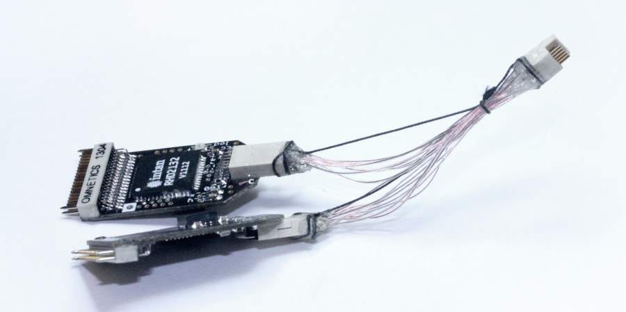
It's not required to twist the LVDS pairs for the short distances in the adapter in our experience.
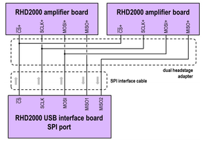
LVDS wiring schematic (source: Intan tech.)
...
Voltage considerations
When running two RHD chips on one cable, the voltage drop over the cable resistance is larger. In extreme cases, such as when using a very long thin wire tether, the VDD can drop close or below to the required 3.2V. Use the on-chip voltage level reader to verify that the chips are receiving adequate voltage. If this is an issue, you can either choose a lower resistance VCC/GND wire pair, and/or slightly increase the supply voltage on your acquisition board by replacing the resistor on the 3.5V headstage power regulator.
Flexible PCB dual-headstage adapter
...