If you didn't receive an assembled acquisition board from Open Ephys, but you still want to use one, do not fear! This page will guide you through the steps necessary to build as many as you need. The amount of time and money invested will vary depending on your approach. But it's unlikely that you'll end up devoting more than 2-3 days of work and $1000 per board (please correct us if these numbers differ from what you actually spend). Given that you'll end up with a fully functional 256-channel electrophysiology acquisition interface at the end of the process, this seems like a pretty good deal!
There are two general approaches:
- Assemble it yourself. This is recommended if you want to end up with fewer than 5 boards, and you have some experience building and troubleshooting electronics. Formal engineering training is not at all necessary, but it might turn out to be frustrating if this is your first electronics project ever.
- Outsource the assembly. This is recommended if you want to build 5 or more boards. It's not really cost effective to build fewer boards this way, but you could do it. This approach doesn't require any technical expertise—it just involves ordering some supplies and coordinating with a fabrication company, such as Advanced Circuits.
We've done both with great results.
For the instructions below, we'll make it clear which steps are only necessary if you're building the board yourself, or only if you're outsourcing the assembly process.
Step 1: Download the files
Clone the acquisition-board GitHub repository, or download it as a zip file.
Step 2: Acquire the raw materials and tools
Open up BOM.csv in Excel or a text editor (or view it on Google Docs). This is a list of all the parts that are necessary to populate the acquisition board PCB. Most of them can be ordered from DigiKey, but some are only available from other distributors. The quantities (column B) are for one acquisition board, so take that into account if you're trying to build multiple boards.
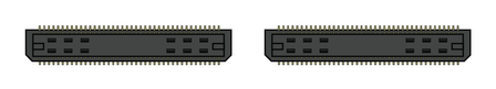
Samtec - For each board, you'll need two of Samtec part #BTE-040-01-F-D-A. These are the connectors that interface with the FPGA. They can be ordered directly from Samtec for around $4 each, or from Opal Kelly for $10/pair. These are referred to as BRD1 on BOM.csv, and as "JP2" and "JP3" on the silkscreen layer of the acquisition board PCB.
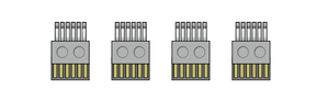
Omnetics - Each board requires 4 of Omnetics part #A79623-001 to interface with the headstages. These must be ordered directly from Omnetics. Not only are they expensive (~$30 each for an order of this size), but they have a 6-week lead time. Sometimes if you hassle them, they'll send them faster. It would be incredibly helpful if someone wanted to act as an Omnetics reseller for neuroscientists. If this is something you might have the resources to implement, definitely let us know! We would do it if we had the money.
Update: As of August 2014, I was able to order four of these connectors with less than one week of lead time.
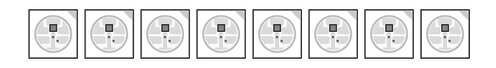
Adafruit - Hat tip to Caleb Kemere for finding these awesome LEDs! The WS2812s contain red, green, and blue LEDs and integrated driver circuitry. They can all be driven by a single data line, using a special programming sequence. You can buy 10 of them from Adafruit for $4.50, but unfortunately they aren't shipped in their original packaging. This means they can be subjected to moisture damage when they're heated up during the soldering process. In our experience, about 1 out of 10 LEDs had to be replaced. If you have the budget for it, or you plan on building a bunch of boards, we'd recommend ordering a roll of 100 or more LEDs from a reseller on Alibaba.
![]()
DigiKey - if you're having the board assembled for you, the fabrication company can take care of the DigiKey order. You'll need to send them the parts from Adafruit, Samtec, and Omnetics, but they'll order everything else based on the Bill of Materials. If you're building it yourself, you'll have to go to the "Fast Add" page and enter the quantities and part numbers for each line item. The resistors and capacitors are cheap, so it's usually worth ordering 50 or 100 of each. For the more expensive parts, having 25% more than you actually need is always a good idea.
Here is a link to a fully filled-out digikey cart. It includes 5-10% extra of the very cheap (<$1) components, but otherwise no more than necessary for a single board.
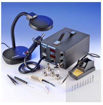
Hot air station - This is necessary only if you're building the board yourself. If you don't have one already, the X-TRONIC Model #4040 is a great deal for only $140. We've used it to make multiple acquisition boards and it works superbly!
Step 3: Order the PCB and Stencil
We recommend ordering your PCBs from Advanced Circuits, since that's what we're using, and we know they can handle our tolerances. The total cost will be about $260 for a single board, as long as you have an academic affiliation to qualify for a discount and a small run. Note that the board is just a bit too big to qualify for the $66 special on multi-layer boards that is prominently mentioned on Advanced Circuits' home page.
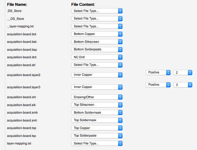
To place this order, you need to first upload the gerber.zip file from the github repository to www.freedfm.com, which is the automatic file checker used by Advanced Circuits. You will need to tell FreeDFM which file corresponds to each layer, and you must specify the inner layers 2 and 3 as "positive polarity". This is shown in the screenshot below.
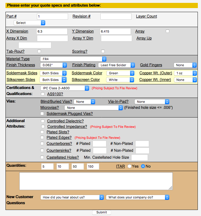
Then enter the following specifications:
- Part Number: 1. This doesn't actually matter, but you can't leave it blank.
- Layer Count: 4
- X Dimension: 6.3
- Y Dimension: 6.415
- Silkscreen sides: Both sides
- Soldermask Color: Green (cheaper) or Black (looks nicer)
- Copper Weight Inner: 1oz
- (Not necessary with FreeDFM) Smallest Hole Size: 0.015
- (Not necessary with FreeDFM) Top SMD Pads: 1058
- (Not necessary with FreeDFM) Holes Per Board: 1370
- ITAR: No
- Quantities: Something like 1/2/5/10 will give you an idea of the relationship between price and order size.
Everything else you can leave as the default. The website will perform some automated checks on the files, which will take about 30 minutes. Then it will produce a quote matrix, in which the price is a function of the production time and the quantity you want. You can change the quantity to 1. The quote will be around $560, but if you contact them and mention your academic affiliation, they should offer you a 50% off coupon code.
In general, Advanced Circuits' prices are pretty competitive with other fab houses. The exception to this is Seeed Studio, which is incredibly cheap. A minimum order for 5 boards will set you back $139.90 (+$31.34 UPS shipping). The turnaround to your door is about 6 days from the time of order. They are not as well made as Advanced Circuits PCB's, but perfectly acceptable. When placing the order, use the following specifications:
- PCB layer: 4
- PCB thickness: 1.6mm
- PCB dimension: 20cm x 20cm
- PCB colour: green (black is + $20)
- Surface finish: HASL (ENIG finish is +$16)
- Panelised PCB's: no
- Remember to specify the inner copper layers as 'positive' after uploading the gerber files
In general, for any vendor,
If you're going to build the board yourself, you'll need to order a stencil and some solder paste. We recommend OSH Stencils, which are designed for small-run fabrications and are priced accordingly. You'll need to upload the same gerber.zip file that you used to print the PCB. Then identify the top solder paste file (*.tsp) as the top stencil and the board outline file (*.oln) as the board outline. Mark all other files, including all solder mask files, as unused. You don't need a bottom stencil because none of the components attach to the bottom of the board. The total cost should be about $21, with an option to buy a "jig" (which helps to position the stencil) for an additional $5. For the solder paste, do yourself a favor and buy SPE-0012 ZephPaste. It's by far the best solder paste we've used. Just remember to keep it refrigerated!
Step 3: Build the board
If you're outsourcing the assembly process, you'll need to supply Advanced Circuits with BOM.csv, centroid_file.csv, and fabrication_drawing.pdf. They'll take care of the rest, once they receive the components mentioned above.
If you're building it yourself, here's what you have to do after your PCBs and stencil arrive:
- As a sanity check, use a multimeter to ensure none of the ground and power pins are connected (you can use the labels that are silkscreened onto the board). It's possible that this could occur as a result of the soldering process, and you want to be sure it's not a problem with the board itself.
- Secure the PCBs to a flat surface.
- Place the stencil on top of the PCB so the holes are aligned with the surface-mount pads.
- Put some solder paste at one end of the stencil, and use a thin sheet of metal (like a razor blade) to drag it across the holes. If you've never worked with surface-mount soldering before, we recommend watching YouTube videos and practicing a bit before you attempt this step. Capacitor C1 is a good one to practice on because it's pretty far from most of the other components.
- Now the fun begins! Place the components in the appropriate configuration, using the silkscreen labels, the acquisition-board.brd Eagle file, and centroid_file.csv as guides. Most components can be placed in any orientation. However, the diodes, and capacitors C22 and C59 must be placed in the orientation indicated on the board. All of the integrated circuits must be placed correctly, with pin 1 in the position marked by the circle on the silkscreen. If you're unsure about how it should look, you can use acquisition-board-populated.png as a reference. Plan on spending 3-4 hours on this step.
- Fire up that heat gun! Remove the nozzle (so the airflow is as wide as possible), then set the temperature to 300º C and the airflow to between 2 and 3. Once it heats up, place the tip about 2-3 cm from the board to heat up the solder. It may take a minute or two for the solder paste to start flowing. But once it does, things start to happen very quickly. As the solder paste melts, it will drag the components into place. Once this happens, move the nozzle to a nearby location, and repeat until the entire board has been soldered.
- Now it's time to troubleshoot. First, check the ground and power pins. If they're connected now, you have a problem. Check each of the SMD pins by eye to look for shorts. If they exist, they're usually easy to spot. If you find one, use a traditional soldering iron to divide the connection. Alternatively, you can use a straight scalpel blade to divide shorts. To do this, first use the heat gun to melt the solder, and then draw the solder blade in between the bridged legs. Because the scalpel blade is stainless steel, the solder will not stick to it. The most common locations for shorts between power and ground are underneath the small decoupling capacitors and underneath the components that have adjacent power and ground pins, such as the voltage regulators and the Adafruit LEDs.
- Assuming you don't have any power-to-ground connections, it's safe to plug in the power cord into the barrel jack on the board. ONLY USE A 5V DC POWER SUPPLY. Once the cord is plugged in, you can check the voltage levels using the holes on the bottom of the board. See the "How it works" page for more details, but most of the voltages should be within 0.1V of the specified level, except that +5va should be about 5.5V. Also, note that the 3.3V level is provided by the FPGA, so this voltage won't be set until the FPGA is plugged in.
Next, add jumpers to the 3-pin headers near the ADC input HDMI (DigiKey part #A26228-ND). We've chosen the ±5V input range as the default by bridging the two pins closest to the edge of the board).
- The final step is to put a drop of epoxy on either side of each Omnetics connector (be careful not the get glue on the pins) in order to keep them stable over many round of plugging/unplugging.
Step 4: Build the case
The shape of the case is specified by an STL (stereolithography) file called acquisition-board-case.stl (github). You can use it to have a case manufactured through a variety of methods, such as cast urethane (we recommend American Precision Prototyping), CNC machining (FirstCut), or 3D printing (Shapeways). Shapeways requires a .dae file, which is also included in the repository.
To order the acrylic top, upload acquisition-board-top-text-ponoko_p1.eps to Ponoko, and select size P1 Opal Acrylic (3 mm / 0.118"). If you're producing multiple boards, you may want to use acquisition-board-top-text-ponoko_p3.eps instead, which has 8 tops tiled onto a single piece of acrylic.
You'll also need 4 screws (92855A310) and rubber feet (9540K11) from McMaster-Carr. Having some extra M3 (2 mm) hex keys (5984A42 from McMaster) will be useful. Depending on the method of manufacturing, you may have to drill out the four screw holes in the bottom of the case. You can use a #37 drill bit, or even better, use a fluted tapping tool (M3 size, 26355A41 should work well - in a low speed electric drill) to prepare the holes.
If you've ordered the case in a color other than white, you'll need to paint the top surface so the glue isn't visible. We recommend Montana Gold spray paint in Shock White, but any bright white paint will do. Make sure to tape the edges so you don't get paint on the sides.
Painting the engraved logo on the acrylic top also looks really nice. We recommend a darker color such as black or blue, using either permanent marker, acrylic or spray paint. Paint the logo before you peel off the protective paper backing - this way there's no way to mess up the logo and you can even use spray paint.
If you're using cast urethane cases, lightly sand the four corners with fine sandpaper so the glue can adhere well.
After the paint has dried, place four drops of thick super glue near the corners of the case top surface, then put the acrylic in place. Make sure the edges of the acrylic are aligned with the case as precisely as possible.
Once the glue dries, you're ready to follow the instructions in the user guide!