Spike sorting & PSTH
Real time spike sorting
Real time spike sorting capabilities will greatly improve the usability of the system for acute experiments. Real time spike sorting algorithms generally fall into two categories, one that use the wave forms directly (e.g. box or vertical line method) and methods that use PCA space.
Currently, both the box method and PCA method are implemented in a new Spike Detector processor:
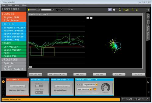
The box method allows to create as many units as you want. Each unit can have one or more boxes. A wave form is considered to belong to a specific unit only if it intersects all of its boxes.
The PCA shows the two largest principal components of the spike wave form covariance matrix. Units are defined as polygons in this space. Each unit can only have a single polygon.
Both techniques can be use in parallel, but the PCA method has priority. In other words, if a spike fits a pca polygon and a box unit, it will be assigned to the pca unit.
Sorted unit information (which electrode, which unique unit ID, color) are stored in the spike object that is passed on the pipeline.
Network Events Source
The network event source listens over the network on a specific port. Implementation is based on the widely used 0MQ library.
To add this capabilities to your graph, dump the network events, and then use the merger utility to merge the two streams.
Network events are useful for sending trial information or other text-based data to GUI (for example, sending updated position of advancers).
Commands can be send directly to a specific module using the reserved keyword "ProcessorCommunication". For example, one can send a string to a specific processor in the graph by sending the string "ProcessorCommunication <processor name> <command>". Processors evaluate incoming messages using the virtual function "interProcessorCommunication".
Special commands are also available:
- "StartRecord", will cause the graph to start recording.
- "StopRecord", will cause the graph to stop recording.
- "SetSessionName <folder name>" will override the default directory where files are stored (from date-time) to <folder name>
- "ProcessorCommunication" <processor name> <string command>, will send a command to s specific processor.
Peristimulus time histogram (PSTH) sink
The PSTH sink module has two main functions:
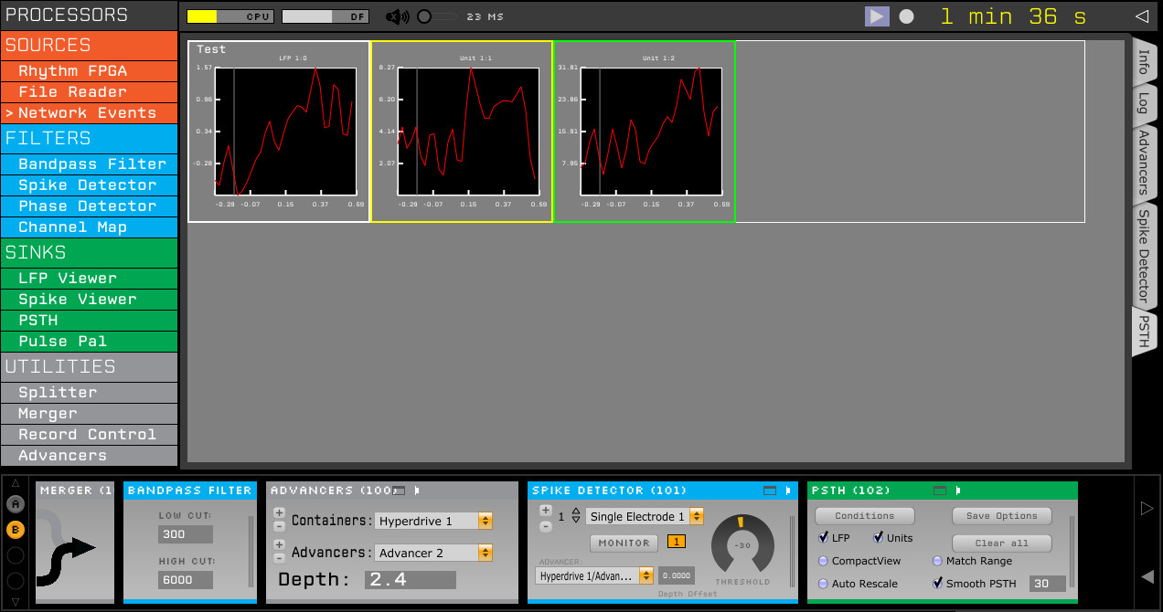
A. It is used to display average firing rate and average lfp, aligned to external events, such as TTL pulses, or more complex trials that are sent over the network (e.g., in the snapshot above, you can see the peri stimulus time histogram for a specific trial type, triggered by a network event. Left most window is the LFP aligned to the trigger, while the yellow and green windows correspond to two isolated sorted units that were defined in the Spike Detector module).
B. It is used to save to disk all pipeline events that were generated after the source (i.e., network events, spikes, etc).
Special mouse buttons:
Left mouse click/drag: zoom in
Right mouse click: zoom out
Double left click: toggle full screen mode
Double right click: clear current plot
A. PSTH functionality
The module uses the following commands that are sent using the Network Events module:
- ClearDesign
- This command clears up all known conditions
- NewDesign <design name>
- This command clears up all known conditions, and set up a name for the active "design". A design has any number of conditions. A condition has any number of trial types, and specific outcomes. See more below.
- AddCondition Name <condition name> TrialTypes <trial types> Outcomes <trial outcomes> Color <R G B> Visible <visibility> SpatialPosition <X Y> Group <group>
- This command add a new condition to the active design. The condition will average spike & lfp information only for trials that belong to the subset of trials defined in <trial types>.
- A trial type is any positive integer smaller than 30,000. Values above 30,000 are reserved for TTL trials that are automatically generated.
- You can further define whether to average a trial or not by its outcome. Outcomes can correspond to correct/incorrect, or any other response the animal makes.
- Outcomes can be any positive integer.
- Color optional, and given by R,G,B, ranging between 0 and 255.
- Default visibility is optional. Visibility value is either 0 or 1, and will determine if this condition is visible by default, or whether the user needs to click on the GUI to make it appear.
- Conditions may have a optional 2D spatial position. This is useful when visual stimulation is delivered at a specific location on the monitor (i.e., saccade to a specific location trials).
- Conditions may be grouped together for easier visualization. For example, you might group a bunch of trials types with no stimulation together and compare them to trials that do get stimulation. Visualization in the future will be able to display them as two curves / rose plots / ...
- TrialStart <trial type, optional>
- This command indicates that a trial has started. You can send (optionally) the trial type here as well. Otherwise, use the TrialType command
- TrialType <trial type>
- This command sends the trial type information of the current running trial.
- TrialAlign
- Spikes & LFP can be aligned not only to trial onset, but to other events (i.e., saccades, lever presses, etc). Use this command to indicate that firing rate should be aligned to the specific time point when this command was arrived.
- If TrialAlign command is not sent for a trial, the default is to average things relative to TrialStart
- TrialOutcome <trial outcome>
- This commands indicate the outcome of the trial.
- TrialEnd <trial outcome, optional>
- This indicates that a trial has finished, with the optional parameter that indicates what was the outcome.
- DropOutcomes <trial outcome codes>
- This will indicate that all trials (regardless of their type) should be dropped and not analyzed if their outcome match the given list. Useful to drop trials in which the animal wasn't looking at the screen.
- This will indicate that all trials (regardless of their type) should be dropped and not analyzed if their outcome match the given list. Useful to drop trials in which the animal wasn't looking at the screen.
For example, a two alternative force choice task, with four conditions can be constructed like this:
NewDesign 2AFC
AddCondition Name GoLeft TrialTypes 1
AddCondition Name GoRight TrialTypes 2
AddCondition Name AllTrials TrialTypes 1 2
AddCondition Name GoRightCorrect TrialTypes 2 Outcomes 2
individual trials can be send as follows:
TrialStart 1
TrialEnd
TrialStart 1
TrialEnd 2
** High precision real time trial alignment
Experiments requiring high temporal precision in trial alignment can be accomplished by sending trial start & trial type information over TCP/IP, but trial align via a TTL pulse on one of the digital input lines.
This needs to be setup in the PSTH GUI accordingly.
An example how to send string messages to GUI from a c++ / matlab session will be available on github.
B. Save to disk functionality
In order to enable the save to disk option, you'll need to use the Record control module and enable the "Events saved by sink" option.
Events are saved in a new file format (0.3). Events can now have variable length, and are thus saved in the following format:
- Event type (uint8) which can have one of the following types:
- SESSION (code 10)
- This will inform that a new recording session has started /stopped
- TTL (code 3)
- This will inform that a digital signal went up/down
- NETWORK (code 7)
- This will inform of a string message arrived via Ethernet
- SPIKE (code 4)
- This will inform of a detected spike
- TIMESTAMP (code 0)
- This will save a pair of software & hardware timestamps, to allow synchornization between software events and hardware events.
- EYE_POSITION (code 8)
- This will inform that a new eye position signal has arrived.
- SESSION (code 10)
- Event size (uint16)
- Event specific data (variable length)
- SESSION
- uint8, representing whether a session has started (value = 1) or stopped (value = 0)
- uint16, representing recording session number
- int64, representing a software timestamp
- TTL
- uint8, representing whether the signal went up (value = 1), or down (value = 0)
- uint16, representing the channel number that was raised/lowered.
- int64, software timestamp
- int64, hardware timestamp
- NETWORK
- <variable length>, representing the incoming message. length of the message is the event size - 8
- int64, software timestamp
- SPIKE
- int64, software timestamp
- int64, hardware timestamp
- int16, sorted unit ID number
- int16, electrode ID number
- int16, number of channels in electrode (typically, 1, 2, or 4)
- float x number of channels: channel gain
- int16, number of points in each channel (typically 32+8).
- <variable length>, representing the spike wave form. actual size will depend on the previous two numbers.
- TIMESTAMP
- int64, software timestamp
- int64, hardware timestamp
- EYE_POSITION
- double, x position
- double, y position
- double, pupil diameter
- int64, software timestamp
- int64, hardware timestamp
- SESSION