Outline
This is a step-by-step on how to build the Hybrid Drive, a chronic implant device combining silicon probes and high density tetrode arrays. Some parts of the Hybrid Drive are based on another implant device for extracellular physiology: the flexDrive. Check this Wiki for more detailed information on the flexDrive. The estimated total time for the building procedure is around 15 hours (best spread across 3-4 days). This protocol has been written in collaboration with Oscar Chadney.
Drive Building
Check/adjust the body of the drive (30 minutes procedure)
The drive body design is the one in use for the flexDrive:
...
Make sure screw holes are clear. If not, use a hand drill (0.45-0-55 diameter) to clear the opening. Note: The angle of the screw relative to the drive body is key for the tetrode adjustment (spring-screw) mechanism.
Make sure the holes in the top part of the body are large enough for a screw or piece of tubing to slot in and secure the EIB to the body (at a later stage, see 2.9).
Clear and/or enlarge guide tube grooves using a scalpel, to ensure that the stabilizer tube fits (see 2.6). Note: If the shape of the holders is damaged in this process, use superglue + accelerator to stick the stabilizer in position.
Enlarge the bottom opening of the body using a dremel mounted with a drill tip (0.5 or 0.9 mm). It’s important that the opening is large enough to fit the bundle, especially if your implant design is made of 2 or more bundles. For CA1 implants, create a diagonal opening (shifted 30-40 degrees from the arms of the body to match the shape of the craniotomy over the hippocampus).
Place screws and lower them until the remaining visible threaded portion of the screw is approximately 3 mm.
Building the bundle tube array - specific 5x3 design (30 minutes procedure
+ 30 minutes waiting time glue)
...
Note: Bundle should be approximately 2.2-2.5 cm in length.
Glue bundle to the drive body (15 minute procedure + 30 minute waiting time glue)
Important: the position of the the array in the drive body is fundamental. Make sure the angle and orientation of the bundle array is correct, and matches your implant coordinates.
...
Apply epoxy around the base, make sure the tube array is aligned as desired, the position can be adjusted as the glue dries. Leave to dry properly.
Apply second layer of epoxy to reinforce the structure.

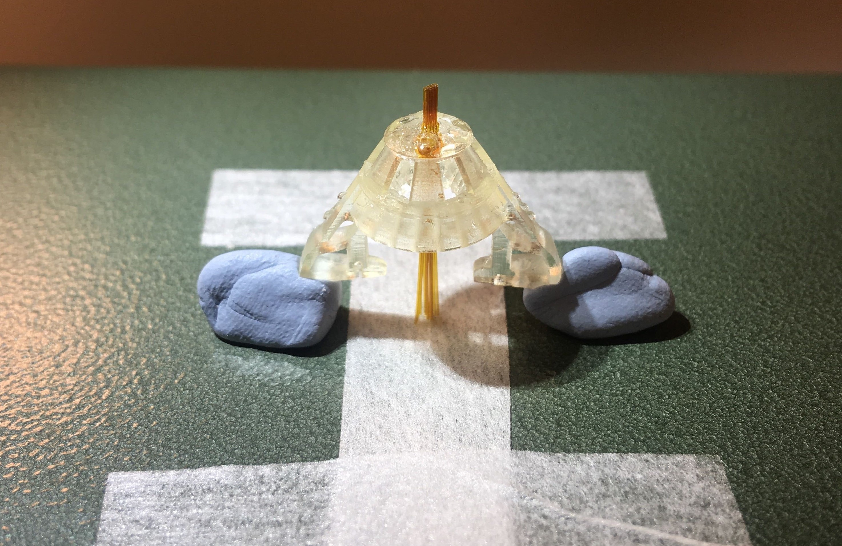
Figure 2: Tube array glued to the drive body.
Assembling the spring
The spring design is the same used for the flexDrive:
...
Solder at the connection point using a minimal amount of solder.
Add spring to the body (15 minute procedure + 30 minute waiting time glue)
Place the drive body upside down, using tack on the arms to hold it in place.
Place the spring so that the bottom and sides align respectively with the bottom and arms of the drive body.
...
Glue the spring to the body using epoxy. Glue all around the bottom opening and add a drop at the level of each arm.
Make sure the spring and drive body are aligned as the glue dries. The position can be adjusted as the glue dries.
Let it dry for at least 30 minutes.
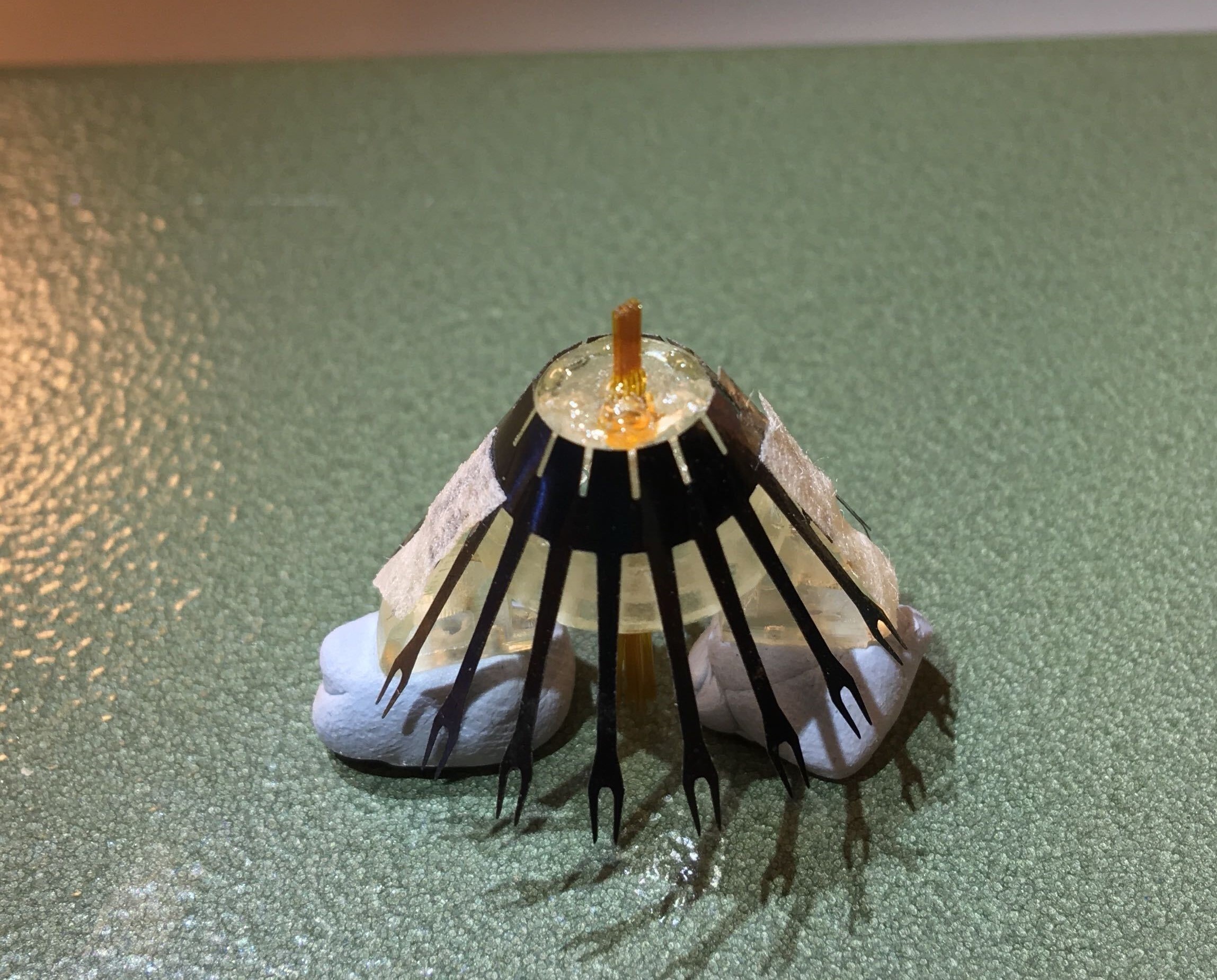

Figure 3: Drive body and spring.
Place and organize guide tubes in the body (60 minute procedure + 30 minute waiting time glue)
Place the drive in its holder. The custom-made holder in the pictures is built from a plastic neck of a soda bottle. Portions of the bottleneck are carved out. Those left hold the drive from the upper arms. Position the washers above each arm and tighten until the drive is stable.
...
Epoxy shuttle tube to spring (and bridge).

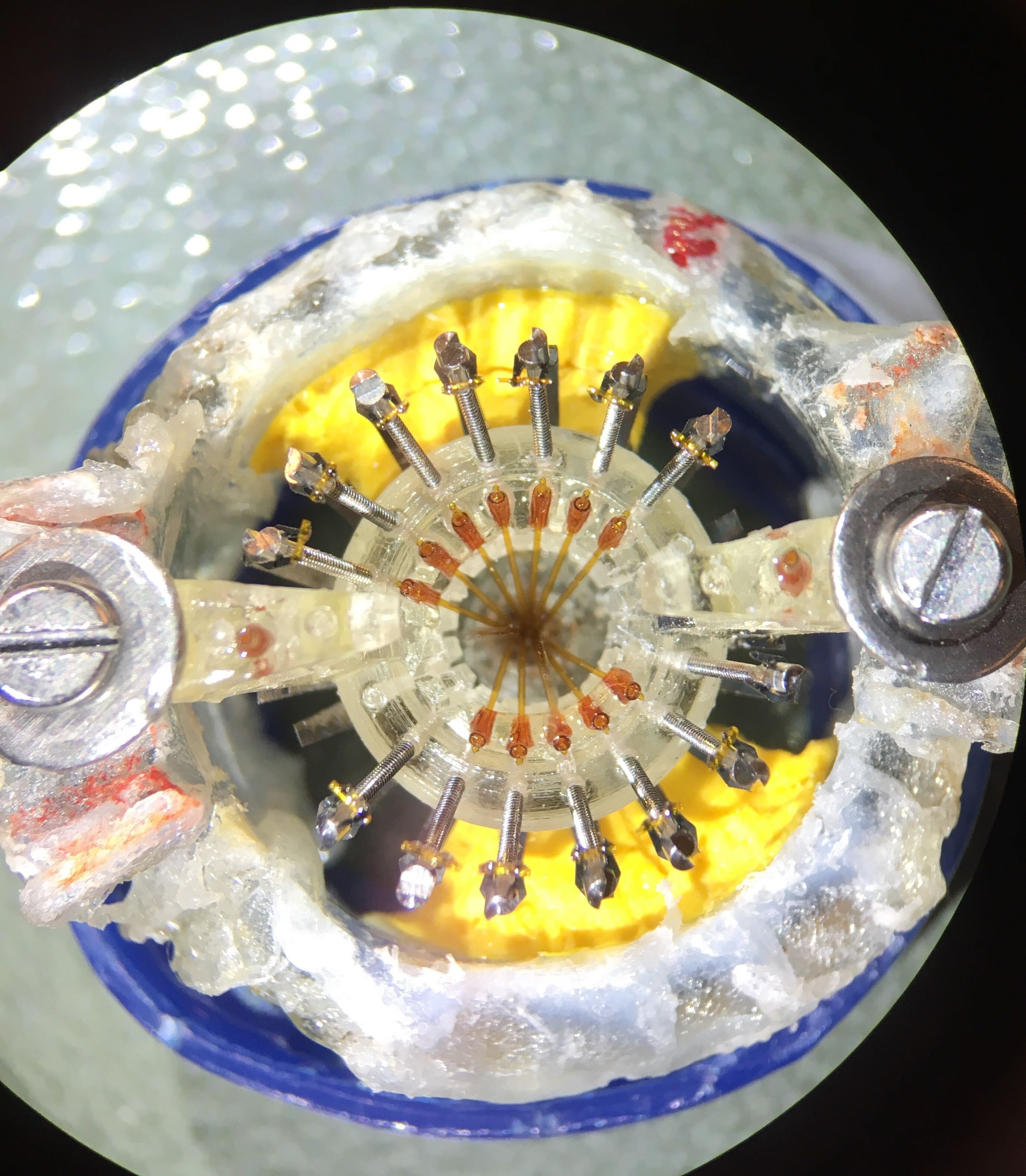
Figure 5: Inner tubes inserted in the guide tubes.
Prepare EIB (15 minute procedure)
The custom EIB is made by ATLAS neuroengineering (https://www.atlasneuro.com/). The current design was studied to include 14 tetrodes and 2 silicon probes. The design of the EIB itself can be adapted, depending on the experimental needs.
...
Note: Be careful not to overheat the EIB or damage the connections on the board.

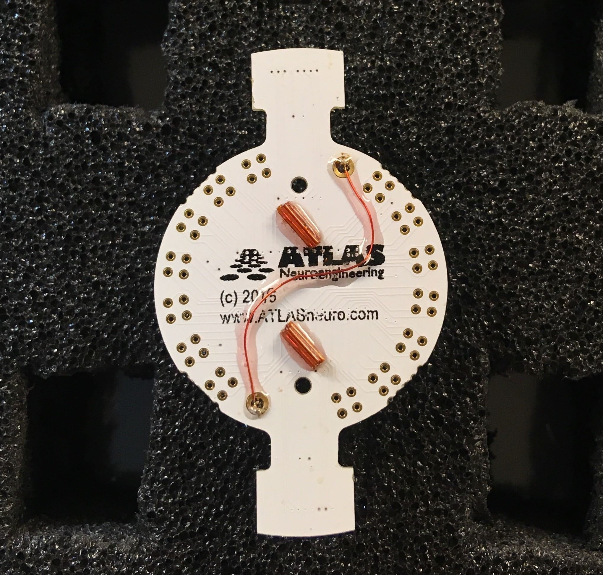
Figure 6: ATLAS EIB with ground connections soldered together.
Probe insertion and placement in the drive body (30 minute procedure + 30 minute waiting time glue)
This is the most delicate step of the procedure.
...
Note: At this stage you can still, carefully, move the probe up and down using forceps (from the black rectangle at the beginning of the probe shank).
Add the EIB (15 minute procedure + 30 minute waiting time glue)
Once the silicon probe is firmly in place (at least 30 minutes of waiting time after the gluing procedure), you can add the EIB to the drive.
...
Once the EIB is firmly in place, plug the ZIF connector of the silicon probe in the ZIF port on the EIB.
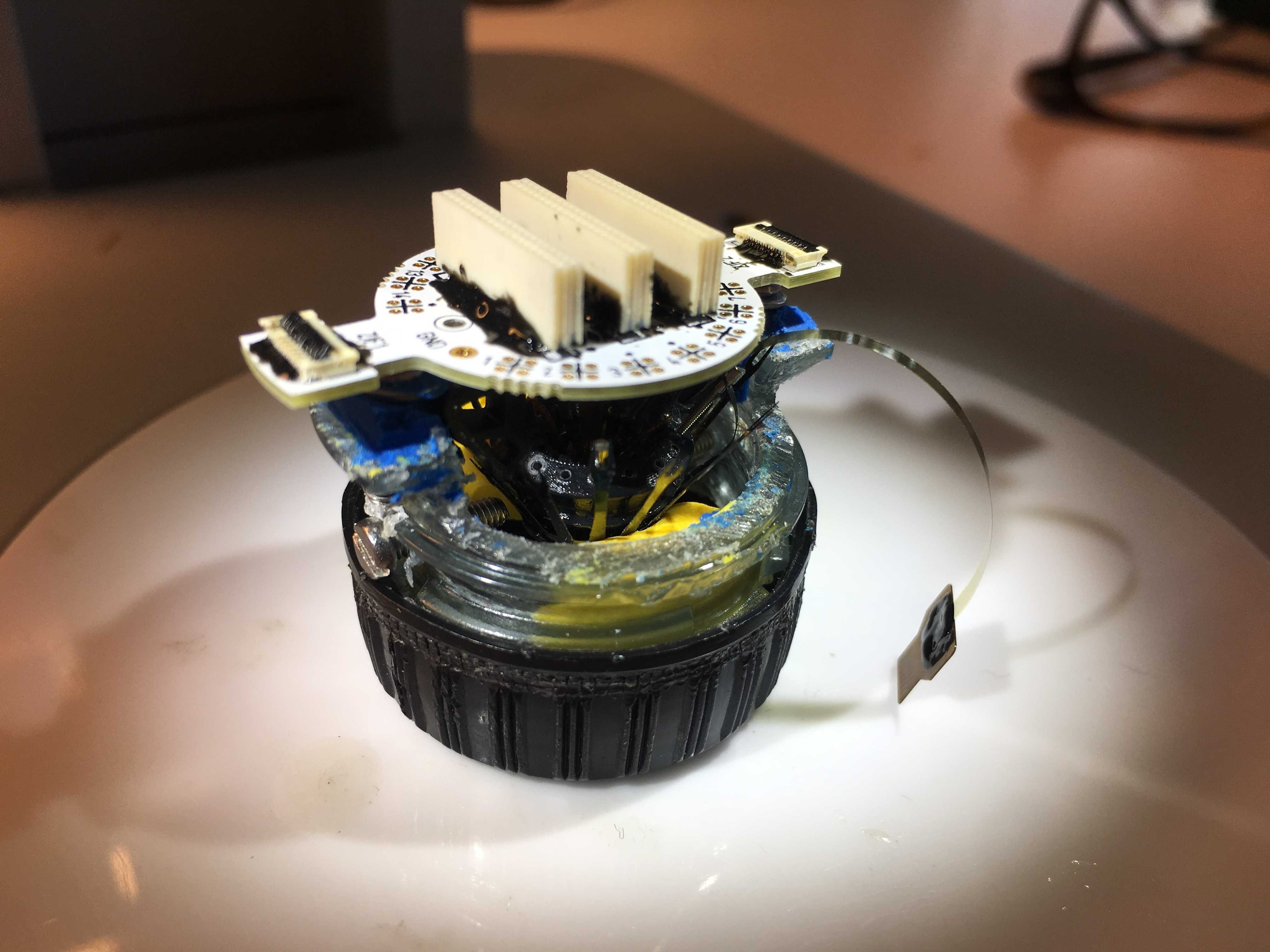

Figure 9: EIB glued to the drive body (probe not connected yet).
Insert and wire tetrodes (4 to 5 hours procedure)
Once the probe is well secured you can start a standard tetrode loading and wiring procedure (see Nguyen et al., 2009 for in-depth explanations). Briefly, insert a tetrode into the shuttle tubes and cut the excess at the bottom of the guide array. Connect each electrode to the EIB using gold pins and glue the top of shuttle tubes with epoxy (to ensure the movement of the tetrode wire via the spring-screw mechanism). In the proximity of the silicon probe pay more attention to the wiring procedure. In order to help reconstruct the final location of the tetrodes keep track of the mapping between the tetrodes position in the guide array and the EIB channels.
...
Figure 10: Drive in the holder for tetrode wiring, with the silicon probe connected via the ZIF connector.
Tetrode cutting (10 minute procedure)
Use serrated scissors.
Before cutting tetrodes, move the silicon probe up. The lowest part of the shank (where elctrodes are) should be entirely inside the guide array. This is fundamental to avoid damage to the shank of the silicon probe during the cutting procedure.
Remove drive from holder.
Place drive on the side with tetrodes parallel to the table with slight inclination to be able to visualise all tetrodes through the scope.
...
Hold scissors with serrated blade on top and smooth blade on the bottom.
Cut tetrodes with a firm, single movement.
The amount left will determine the total movement possible inside the brain. This varies depending on the target area. For the CA1 pyramidal layer 2.5 mm are enough.
Add extra layer of epoxy between EIB and drive body to strengthen the structure.
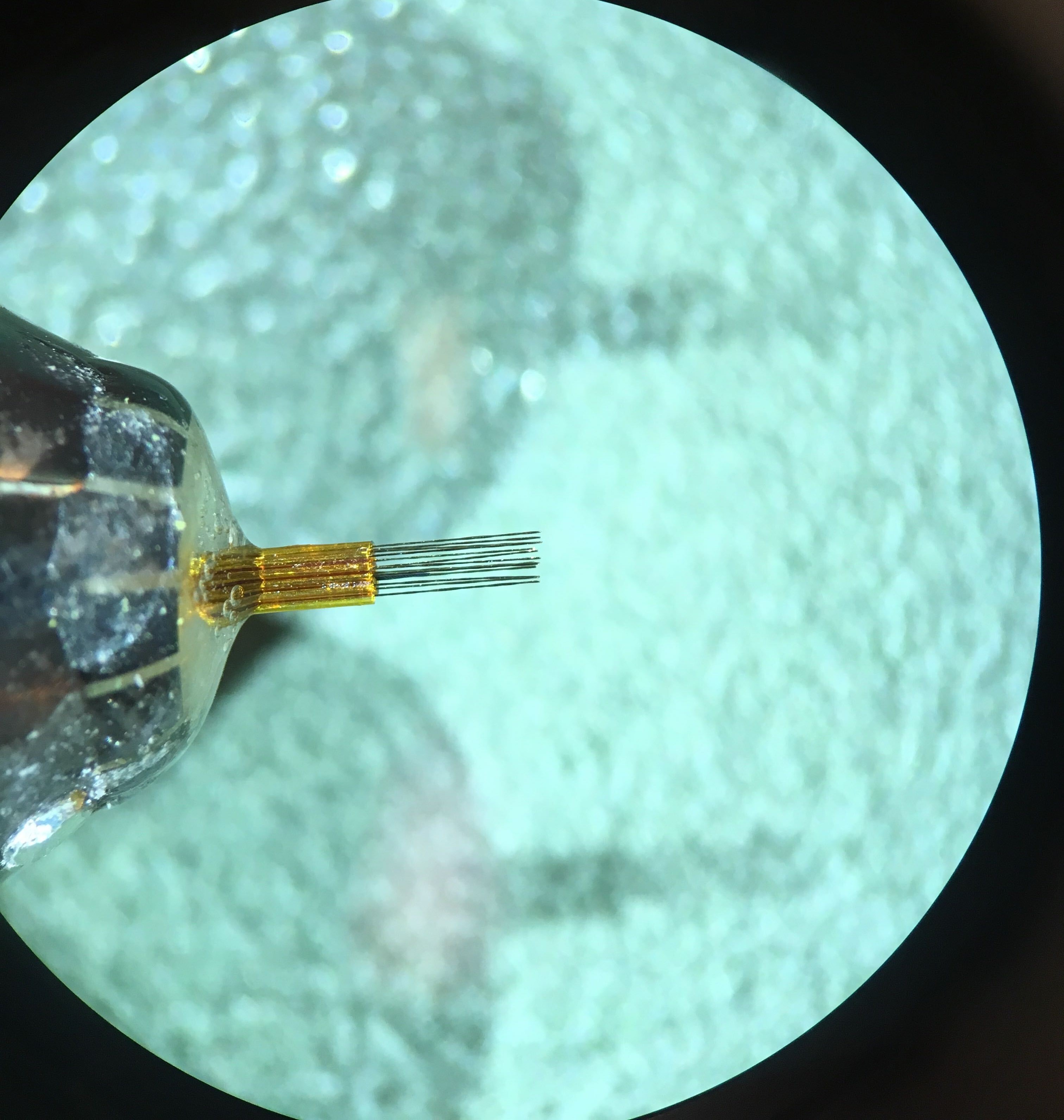

Figure 11: Tetrode tips at the bottom of the drive, after cutting procedure.
Plating (60 minute procedure)
Plate the tetrodes.
Note: At this stage the tip of the silicon probe is still inside the tubing structure.
Once the tetrodes are plated you need to move them back inside the tubing structure of the array. You can carefully move them one by one using forceps (from the top, near the inner tube and EIB).
Once all the tetrode tips are even with the bundle array you can glue the tetrodes in position.
Gluing the silicon probe in its final position (10 minute procedure + 30 minute waiting time glue)
This is the final step before shielding. Once you glue the probe in position you will only be able to move it via the spring-screw mechanism. After a few tests, we realized that it is safer (and more efficient) to set the silicon probe in its final position during drive building (rather than lowering it into the brain after the implant surgery).
...
Note: Be careful not to spread glue along the silicon probe shank. It will hinder the movement mechanism.
Shielding (45 minute procedure + 30 minute waiting time glue)
Shielding is the last step of the Hybrid Drive building procedure.
You can use a cone shape plastic sheet to cover the body following the same shielding design of the flexDrive: https://open-ephys.atlassian.net/wiki/spaces/OEW/pages/950325/6+-+Shielding+ the+drive.

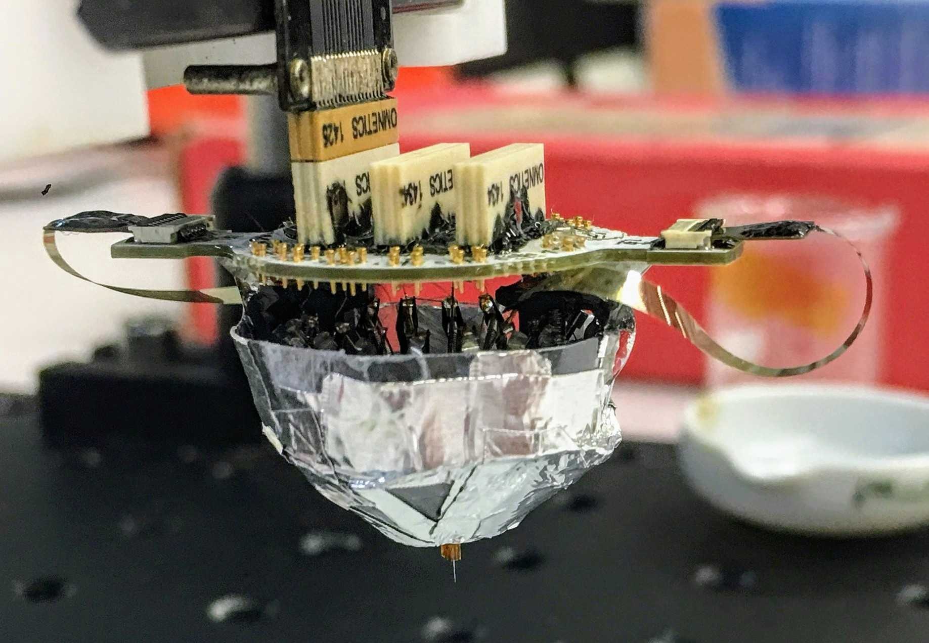
Figure 12: Hybrid Drive with the body shield glued to the drive body.
...
Note: It is important that probe ZIF connector does not touch the protection when you insert it. If your protection cones are too tight, repeated collision in the homecage (once the drive is implanted on the animal) will damage the ZIF connector.
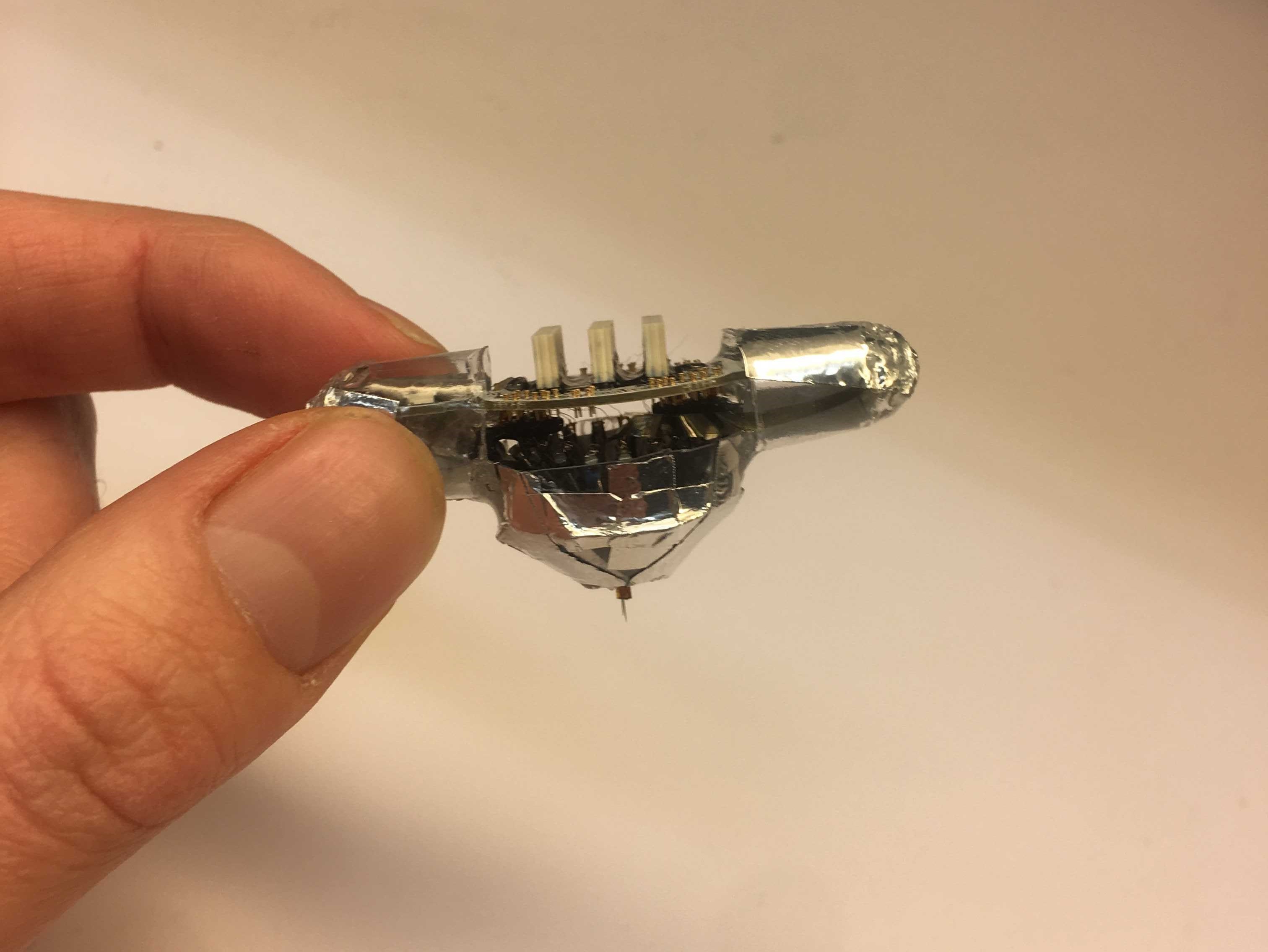

Figure 13: Hybrid Drive with the lateral cone protections glued, ready for implant surgery.
...