Before you begin
Equipment needed for this job:
- Completed guide tube bundles (Fig 0A; click here for building instructions)
- Completed targeting cone (Fig 0B; click here for 3D printing instructions)
Supplies needed for this job:
- Plungers Plunger tubes made from 4"-6" lengths of Type 304 Stainless Steel Tubing, with diameter of each collar matching that of the guide tube bundle that it will be used to insert:
9x bundle: 13G, .095" OD, .071" ID, .012" Wall (McMaster-Carr 8988K32)
7x bundle: 16.5G, .062" OD, .052" ID, .005" Wall (McMaster-Carr 8988K36)
4x bundle: 17G, .058" OD, .042" ID, .008" Wall (McMaster-Carr 8988K45)
Procedures
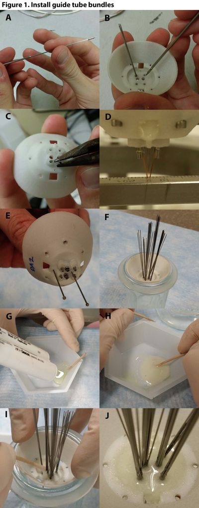
Clear out the targeting cone holes (Fig 1A). Run the plunger back and forth through the guide tube collar hole, to make sure that the collar will fit snugly into the hole (don't widen the hole too much or the fit will be too loose)- Insert the bundle into the plunger (Fig 1B1A), Insert the long ends of the bundle guide tubes (those farthest from the collar end) into the plunger tube, and insert push them all the way in until the collar is flush (or nearly flush) with the plunger (as far as it will go in).
- Insert the bundle collar into the targeting cone (Fig 1C1B), Holding the plunger, insert the guide tube collar into its assigned hole in the targeting cone. Push it through the base until it extends 2-4 mm from the other side.
- Repeat steps #1 to #3 until all bundles are inserted in the targeting cone (Fig 1C), Holding the plunger, insert the guide tube collar into its assigned hole in the targeting cone. Pus
- the guide tube tips extends 1.5-2.5 mm from the bottom of the cone (you can use the targeting cone design tool to help you decide the best length of the projection). You can either insert the guide tube bundle from the top side (i.e., inside) of the targeting cone (as shown in FIg. 1B), or from the bottom side (not shown), whichever is easier. In either case, you should try to insert the guide tube bundle as close to the proper orientation as possible, so that the next step (step 3) may not be necessary.
- Adjust the orientation of the guide tube bundle (Fig. 1C). If the orientation of the guide tubes is not quite accurate, then you can try to turn it to the proper orientation with a tool (like forceps or pliers). But be careful not to crimp the guide tube collar while you are doing this, or you may distort the shape of the guide tube bundle.
- Check the alignment of the guide tube bundles (Fig 1D). Repeat steps 1-3 until all guide tube bundles have been inserted. Then mount the