MilMax connectors
- Jakob Voigts
Preparation of electrode interface for 64-channel (16 tetrodes) flexDrive with Mill-Max connectors adjusted for Axona recording system
Materials
Four 18-pin Mill-Max sockets. Two metal pieces (3 × 50 mm) cut from copper sheet 0.3 mm thick. One single use injection needle 0.8 × 40 mm. Cyanoacrylate glue.

(click on any image to see the full size version)
Step 1
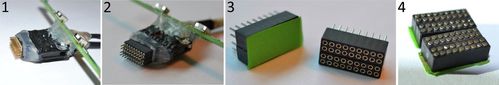
(1 and 2) Attach sockets to pins of your Axona headstage to provide best position of sockets in your interface for currently used cable. Glue sockets together by applying small amount of cyanoacrylate glue into the cleft between black plastic parts of sockets. (3) Protect against dust female side of sockets with the tape and (4) trim male part of connectors to reduce their weight, size and prepare terminals for soldering tetrode wires.
Step 2
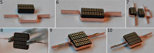
(5-7) Bend copper stripes around connectors as shown on the picture. (8) Put two bent parts together with sockets inside the frame and solder them using forceps. (9-10) Soldered frame.
Step 3
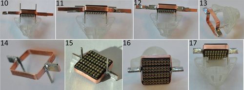
Cut from the needle two stainless steel tubes and (10) place them in the middle between sockets and place where two parts of frame come together. Later place steel tubes in the body of flexDrive in the holes for screws for EIB to ensure their proper position for soldering. Adjust optimal height of your interface and (11) bend steel tubes in chosen place. (12) Solder tubes to the frame carefully as shown on the picture (use forceps to prevent earlier soldered frame to fall apart). (12) When tubes will be well soldered to the frame (13) cut extended parts to fit diameter of flexDrive. (15) Glue well sockets to the frame using cyanoacrylate glue. (16 and 17) Check again if your interface fits well your flexDrive body.
Step 4
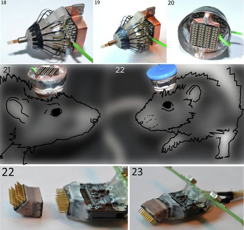
(18 and 19) After mounting tubes, electrodes, spring and screws on your flexDrive body solder copper grounding wire to the fifth middle row of connectors in all sockets of your interface. Later place interface in comfortable position under the angle close to flexDrive and solder tetrode wires to the interface (tetrodes are organized in rows 1-4 and 6-9 on each of two prepared and mounted in the frame 32-channel sockets, respectively). Ensure that free parts of tetrode wires have proper length to solder them to not yet mounted on flexDrive interface. After all tetrodes are soldered in the correct order you can use liquid transparent nail polish to insulate and protect fragile parts of tetrode wires in the place of soldering. You can use syringe with needle to apply it - thick layer is preferred (but be careful not to exceed the maximum amount otherwise it can flow out and get into the female socket pins or protect female parts of pins with tape before). Next, place steel tubes inside the holes for screws supporting EIB on the top of your flexDrive. Glue them well with cyanoacrylate glue. After the glue is dry, fill the space between arms of the drive body, steel tubes and lateral parts of connector with small amount of dental cement to stabilize construction. (20) Add enclosure and fill with dental cement the space between enclosure and lateral parts of interface to further strengthen whole construction. Now your interface is ready and flexDrive can be implanted (21). (22) After implantation prepare protective cap made of plastic and male Mill-Max connectors.
Prepared interface frame weigh about 620 mg and trimmed Mill-Max sockets 1600 mg – whole interface about 2.2 g, however, as tested in our laboratory (Trinity College Institute of Neuroscience, Dublin, Ireland) implanted flexDrive is easily carried by adult rat. (23 and 24) Interconnector made of two Mill-Max sockets and male connectors that helps in recordings in environments with walls by placing headstage behind rat’s head.