Rhythm FPGA
- Josh Siegle
- Josh Siegle
- Aaron Cuevas
IMPORTANT: The Open Ephys GUI documentation has migrated to a new site – please visit https://open-ephys.github.io for the most up-to-date information.
Description
This source can receive data from any FPGA running Intan's "Rhythm" firmware. It is compatible with both the Open Ephys acquisition board and the Intan RHD2000 Evaluation board.
See here for info on data acquisition latency
Features
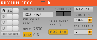
Here are the current features of the Rhythm FPGA module (from left to right, top to bottom):
Data stream configuration
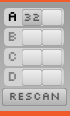
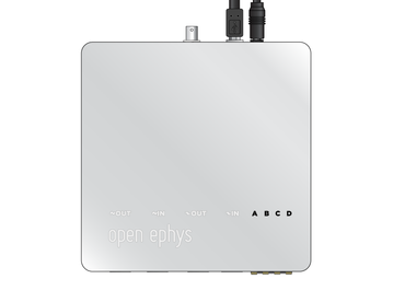
On the left-hand side of the module, there are slots for each of 8 "data streams" (A1, A2, B1, B2, etc.). Each row corresponds to one 12-channel Omnetics connector on the input board (see the bottom right of the images of the acquisition board below; from left to right, there are A, B, C, and D), and each column corresponds to one headstage on that input. Up to two headstages can be connected to each input using a dual headstage adapter. The module will automatically detect headstages that are connected. However, if you add or remove headstages after the module has been loaded, you need to press the "RESCAN" button. Clicking on the button for one of the detected headstages will toggle it between 32-channel and 16-channel mode. This is necessary because the difference between 16-channel and 32-channel headstages cannot detected in software, and has to be selected manually.
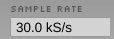
Sample rate selection
Sample rates between 1 and 30 kHz can be selected with this drop-down menu. This will determine the sample rate for all headstages, digital inputs, and ADCs.
Bandwidth interface
Used to determine the settings for the analog high and low cut filters on the Intan chip. Because only certain values are possible for each, the number that appears may be different from the number you typed in; the chip will automatically select the nearest value, and that will be indicated in the GUI. KNOWN ISSUE: the default values are actually 1.1 and 7603.8 Hz, not 1 and 7500 Hz, as indicated by the interface when it's first initialized.

DSP button
in addition to the analog filters, the Intan chips also have an on-chip DSP high cut filter for removing the DC offset on each channel. This can be toggled on and off by clicking the "DSP" button (yellow = on), and the cutoff frequency can be changed by typing a value into the associated text box. Again, there are only certain values for the cutoff frequency; the chip will choose the one closest to what you selected and return this value to the GUI.

Audio output
This is for audio monitoring of channels. There are two ways to use audio output.

Hardware audio monitoring
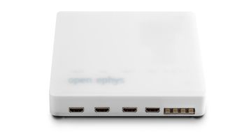
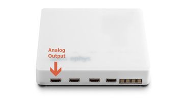
The "AUDIO OUT" interface will allow you select up to 2 channels to preview in real time, directly from the acquisition board/evaluation board.There is an audio jack (see the red circle in the picture below) that's mirrored to the first two analog output channels (CH1 and CH2 of the Digital & Analog I/O for L and R sound outputs when connected to HDMI port for analog output — it is the leftmost HDMI port; see a picture below). To select a channel for monitoring, click on one of the two "AUTIO OUT" buttons, then open the Channel Selector drawer on the right of the module. Make sure the "PARAM" tab is selected, and click on any of the available channels. This can be repeated for the other button, such that the left and right audio outputs can be set to different channel.
NOTE: Currently only two channels can be selected. With firmware updates, it is possible to increase this up to 8 channels. 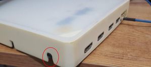
Software audio monitoring
Alternatively, you can specify one or more channels in the "AUDIO" tab of the Channel Selector drawer to each of the AUDIO OUT buttons and control the volume and the threshold (Gate) by adjusting the two sliders at the top of the application window (see below).
NOTE: This method may suffer a bit from latency and artifact, compared to hardware audio monitor using the "PARAM" tab.
Noise slicer
Sets the threshold for the noise slicer on the hardware audio outputs (sets any values below threshold to zero, to improve the signal-to-noise ratio). In practice, this doesn't work particularly well.

ADC selection
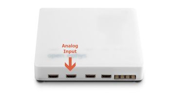
Pressing the "ADC 1–8" button toggles the ADC inputs on and off. If the button is off (gray), the ADC channels on the acquisition board/evaluation board will be discarded. If the button is on (yellow), they will be sent as parallel data channels, with the same sampling rate as the neural data. A Digital & Analog I/O board needs to be connected to the second HDMI port from the left.

DAC TTLs (UNTESTED)
What does this actually do?
DAC High-pass filter (UNTESTED)
Sets the high-pass filter cutoff for the DAC outputs
TTL settle (UNTESTED)
Ties one of the digital inputs on the acquisition board/evaluation board to the "fast-settle" functionality of the Intan chips. If the selected digital input channel goes high, it will trigger the reset of the amplifiers across all headstages.
Impedance testing
To open the impedance testing interface, click the "window" or "tab" buttons at the top of the module. Clicking the "measure impedance" button will test the impedance for all of the channels. IMPORTANT: the GUI will appear to freeze while impedance testing is happening; this is something we know about and are working to fix.
Important things to keep in mind
By default, all of the channels from the Rhythm FPGA module will be recorded. If you want to disable recording for certain channels, this can be done in the "REC" tab of the Channel Selector. As of GUI version 0.3.3, the ADC channels are automatically recorded after they are enabled.
Any data coming in through the digital inputs of the acquisition board/evaluation board will be saved as events in the all_channels.events file (when using Open Ephys data format) or the KWIK file (when using Kwik format). There will be one event when a channel goes "high," and another when it goes "low." This will happen automatically, there is no configuration necessary. It's not currently possible to disable event saving for particular channels; anything that comes in on the 8 digital inputs will be saved.
USB 3 (XEM6310-LX45) board support
We've added support for the newer USB FPGA boards, making it possible to acquire data from up to 512 channels. This could also somewhat reduce the latency (link).
If you plan to use a USB3 board, keep in mind the following recommendations and known issues:
- USB3 acquisition is currently fully tested on Windows. It might still not work properly on Linux or Mac (check additional note for Linux users).
- USB3 boards needs to use the
rhd2000_usb3.bitbitfile. If both bitfiles are present on the executable folder, the GUI will automatically pick the one it needs. Trying to load the USB2 bitfile on an USB3 board or viceversa will result in an error. - You need to install the
FrontPanelUSB-DriverOnly-4.4.0.exedrivers from theResources/DLLsfolder and then re-connect the board. - Plugging an USB3 board on a USB2 port can result on strange behaviours. At the very least, it won't enforce the 256 channel limit as it does with an USB2 board.
- You'll need a fairly powerful machine to be able to acquire 512 channels (Intel i7 at 3.4GHz or equivalent with an SSD disk are recommended).
- The only supported format for writing large amounts of channels is the HDF5 based Kwik format. Since "Open ephys" format opens a file for each channel it can cause a crash when recording a high channel count.
- If the CPU load indicator in the GUI reaches 100%, even if it's in a spiking manner, double check your data timestamps for possible missing blocks.
- Due to the high load caused by 512 channel acquisition and recording, we do not recommend running any extra online analysis or processing apart from basic visualization, as it is easy to overload the CPU, causing data loss.
Linux users and USB3 boards
The latest version of libokFrontPanel.so library, which is required for USB3 support, is linked to libudev0. However, Ubuntu 14.04 and onward only supply libudev1. For this reason, we are supplying both old and new copies of the library. The old, USB2 version is located in Resources/DLLs/ libokFrontPanel.so. The USB3 version is located in Resources/DLLs/Linux-usb3/[x32 or x64]/libokFrontPanel.so. To use them just copy them to the executable folder.
If you're using Ubuntu 14 and want to test USB3 support without downgrading your OS there is a workaround consisting on creating a softlink to libudev1 mimicking the libudev0 path. This can be done by the command "sudo ln -s /lib/[i386 or x86_64]-linux-gnu/libudev.so.1 /lib/[i386 or x86_64]-linux-gnu/libudev.so.0", using i386 or x86_64 depending on your architecture. Keep in mind that this is a very hackish approach and can cause unknown instabilities on your system.
Debian sid has libudev0 in multiarch repositories, so you can apt-get it as long as multiarch is enabled. Everything seems to work then.