Neuropix-PXI
- Josh Siegle
- Pavel Kulik
IMPORTANT: The Open Ephys GUI documentation has migrated to a new site – please visit https://open-ephys.github.io for the most up-to-date information.
This source module communicates with a PXI-based data acquisition system for Neuropixels 1.0 probes. It can acquire data from up to 16 probes simultaneously.
For information on how to install the Neuropixels version of the Open Ephys GUI, please see this page.
Hardware requirements
- One PXI chassis (so far we've tested National Instruments PXIe-1071 and PXIe-1082)
- One PXI remote control module, housed in the PXI chassis (we've tested National Instruments PXIe-8381 and PXIe-8398) – requires NIDAQmx driver
- One PCIe interface card, housed in the computer (we've tested National Instruments PCIe-8381 and PCIe-8398)
- (optional) One PXI-based analog and digital I/O module (we've tested National Instruments PXI-6133)
- Cables to connect the remote control module to the PCIe card (e.g., National Instruments MXI-Express Cables, Gen 3 x8)
- 1 or 2 Neuropixels PXIe modules (available from IMEC) – requires Enclustra driver, available when downloading the GUI
- 1 to 8 Neuropixels 1.0 cables (black + yellow twisted pair, USB-C to Omnetics, available from IMEC)
- 1 to 8 Neuropixels 1.0 headstages (available from IMEC)
- 1 to 8 Neuropixels 1.0 probes (available from IMEC)
If you've tested the GUI with PXI hardware from a manufacturer other than National Instruments, please let us know. Other possible hardware configurations can be found on the SpikeGLX GitHub – we plan on testing these with Open Ephys as soon as possible.
Minimum computer specifications
So far, this module has been tested on a computer with the following hardware:
- Dual Intel Xeon 4-core CPU (2.60 GHz)
- 64 GB RAM
- Intel SSDC2BX800G4 (boot drive)
- Samsung SSD 850 EVO 1TB (data drive)
- NVIDIA GeForce GTX 1070 graphics card
- Windows 10 operating system
It's highly likely that other types of machines will be fine as well, so please get in touch once you've tested them!
Connecting to the PXI system
Before using this module, make sure you've followed all of the steps in the Neuropixels 1.0 Manual to set up and configure your hardware.
Once your PXI system is up and running, you can drag and drop the "Neuropix-PXI" module from the Processor List onto the Editor Viewport. The GUI will freeze while it searches for available probes. After that, the module will be grayed out while the probes are initialized and calibrated.
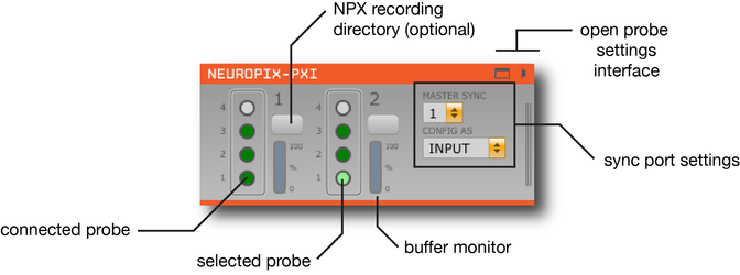
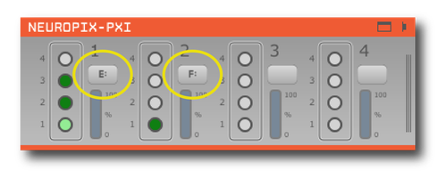
The editor will automatically create a probe selection interface for each basestation that's available. Each basestation can communicate with up to 4 probes, indicated by circles. When the probes are initially detected, they show up as orange. Unconnected probes appear gray. Once they are initialized, connected probes become filled in with green. When the currently selected probe turns light green, it means that all settings have been properly loaded, and the plugin is ready to begin data acquisition. In this example, there are 6 probes connected, and the probe on basestation 2, port 1 is selected.
Besides the circles representing the four probes, each basestation column has a button to select a folder for writing data (if using the compressed NPX format), and a monitor to indicate buffer filling (from 0-100%).
On the right-hand side of the editor, there's an interface for updating sync settings (more information below).
Configuring probes
To open the probe settings interface, press the "window" or "tab" button in the upper-right corner of the editor.
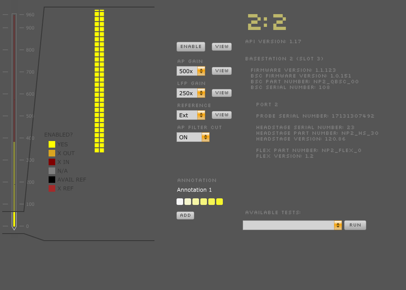
Each probe has its own interface for updating settings. Selecting one of the buttons in the module's editor allows you to access the parameters for a particle probe.
The available settings are:
- AP Gain (amplifier gain for AP channels, 50x-3000x, default = 500x)
- LFP Gain (amplifier gain for LFP channels, 50x-3000x, default = 250x)
- Reference (External, Tip, plus channels 192, 576, or 959, default = External)
- AP Filter Cut (ON = 300 Hz high-pass filter active, OFF = filter inactive)
You can also select/deselect electrodes from different banks. By default, the bottom 384 eleectrodes are selected. To select electrodes farther up the probe, use the interface on the left to scroll to the electrodes you want to activate and click the "ENABLE" button. Selecting electrodes on one bank will deactivate the associated electrodes on the other two banks.
Important note: Saved configurations associate settings with particular probe serial numbers, rather than PXI ports. If you've changed the order in which probes are connected to the PXI basestation, please be aware that the settings will be loaded based on probe serial number.
Calibrating probes
Probes will be calibrated automatically when the plugin is loaded, provided that calibration files are stored in the correct location:
...\<open-ephys-executable-folder>\CalibrationInfo\<probe_serial_number>
These files can be obtained from IMEC for every probe that you've purchased. There should be two for each probe:
- <probe_serial_number>_ADCCalibration.csv
- <probe_serial_number>_gainCalValues.csv
If these files cannot be found, the following warning will pop up:
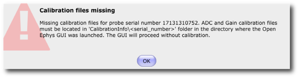
It's fine to use uncalibrated probes for testing, but calibration is strongly recommended prior to recording actual data.
Important note: It's normal for there to be a delay of up to 10 seconds when starting acquisition for >3 probes simultaneously, as the GUI builds the signal chain for thousands of channels. We are working on creating a progress bar so there's less ambiguity about what's happening after you hit the "acquire" button.
Selecting individual data streams
By default, the Neuropix plugin will send data from all probes through the GUI signal chain. Because each probe generates 384 channels of AP-band and 384 channels of LFP-band data, the number of channels being pushed through the signal chain is 768 x N, where N is the number of connected probes. This adds up quickly, and can lead to heavy CPU usage when recording from many probes simultaneously (as indicated by the Open Ephys CPU monitor, which measures the fraction time of each buffer callback spent processing data, and by the Windows Task Manager CPU meter, which measures overall CPU usage).
To save CPU cycles during acquisition, it's recommended to use a Stream Muxer (stream multiplexer) plugin immediately to the right of the Neuropix-PXI plugin. This will allow you to select one probe to send through the signal chain. All channels will still be recorded, but you'll only be filtering, referencing, visualizing, etc. one probe at a time.
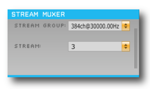
When this processor is in the signal chain, you must pre-select the AP band (30 kHz) or LFP band (2.5 kHz) before starting acquisition. Once acquisition is active, you can toggle between different probes by selecting different streams.
Because the streams from each probe are asynchronous, downstream processors may end up receiving out-of-order timestamps when switching between streams. For open-loop visualization, this shouldn't be an issue. But if you're doing any closed-loop feedback that requires the data from multiple probes, please let us know.
Visualizing data
Drag and drop an LFP Viewer to the right of the Neuropix or Stream Muxer module in order to display continuous signals from the probe. You can visualize data from the AP band (Sub-processor 0) or LFP band (Sub-processor 1). Events coming from the SMA connector will be overlaid in yellow. You can select different probes to visualize by clicking on the button corresponding to each probe in the PXI plugin editor.
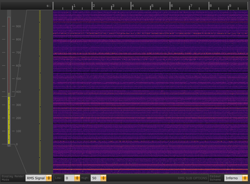
Alternatively, you can use the Probe Viewer plugin to visualize data as a heatmap across all channels:
Synchronizing with other inputs
Sync signals can be input or output through the SMA connectors on each basestation. The signal from the "master" basestation will be sent to all of the probes. This signal can either be generated externally, or be generated by the basestation itself. By default, the GUI expects an external sync input on the leftmost basestation, but this can easily be updated through the sync port interface in the plugin editor.
If you're using multiple probes, it's mandatory to have some sort of sync signal, because the probe data streams are not guaranteed to be at the same sample rate. It's fine to use an internally generated sync signal from one of the basestations. Make sure you're not using an external sync if you don't have anything connected to one of the SMA ports.
To acquire additional digital, as well as analog, inputs you can use a NIDAQmx Source Module. Inserting this module into the signal chain will create a parallel data stream for channels coming from NI hardware, which you can visualize with a separate LFP Viewer. If you're using PXI-based NI hardware (e.g., PXI-6133), the first digital channel will be connected to the sync line of the Neuropixels basestations. If you're using USB-based hardware, you'll have to make sure that one of the digital inputs is connected to the SMA connector on the Neuropixels basestation, to ensure that you can synchronize your data offline.
Saving data
You can use the GUI's built-in binary format to record data. When you press the Record button, the GUI will automatically save separate .dat files for the 384 AP channels (Neuropix-3a-10X.[0,2,4,...]) and the 384 LFP channels (Neuropix-3a-10X.[1,3,5,..]) for each probe. A set of events for each probe will also be saved with the same timebase as the AP channels. The same event channel is shared across all probes. However, because each probe has its own set of timestamps, the event times can differ from probe to probe.
Important note: The GUI will crash if you attempt to record using the Open Ephys data format, which opens a separate file for each channel. Only use the binary format when recording Neuropixels data.
If you're recording from multiple probes, you may want to save the data to compressed NPX format, and convert to .dat files offline. This is helpful if you want to distribute your files across multiple hard drives (which is not currently possible with the GUI's default recording system). One hour of data from one probe takes up about 80 GB, so 8 probes will fill up a 1 TB SSD in about 1.5 hours.
Configuring this requires the following steps:
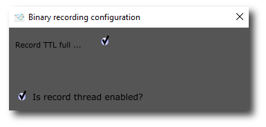
First, turn off the GUI's built-in recording by clicking the "R" button in the control panel to bring up the recording configuration interface

De-select the checkbox for "Is record thread enabled?"
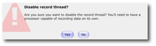
This will bring up the following warning. Click "Yes" to proceed.
Next, select a data directory for each basestation, using the buttons in the Neuropix-PXI editor:
The top-level volume will be displayed inside the button once a data directory is selected. It's possible to record data for each basestation to a separate directory.
To convert the NPX files to the binary format (.dat files), use the "NpxExtractor" command-line tool found in the Tools/NpxExtractor directory:
> NpxExtractor.exe <input_directory> <output_directory>
Saving signal chains
We recommend selecting "File > Reload on startup" to make sure all of the settings (especially data directories) are re-loaded the next time you start the GUI. You can also save signals chains to individual .xml files for loading on demand.
Listening to spikes
Before you can use the audio monitor, you need to add a Bandpass Filter to your signal chain in order to remove the DC offset present on most channels. Place a Bandpass Filter plugin to the right of the PXI module (or the Stream Muxer, if you're using multiple probes), then open the "parameters" drawer by clicking on the 3 lines on the right of the module. Switch to the "AUDIO" tab. Clicking on individual channels will send them to the computer's audio output. The volume slider must be moved to the right before you'll be able to hear any output from the GUI.
Important note: The GUI will crash if you attempt to listen to AP band and LFP band channels simultaneously, so make sure you are only listening to channel 384 or lower. If you have a Stream Muxer in the pipeline, this won't be an issue.
Removing noise
The best way to remove noise is through proper grounding, shielding, and referencing. However, residual noise can be removed by placing a "Common Avg Ref" plugin in your signal chain. Using this plugin will not affect the saved data.
Important note: The GUI will crash if you attempt to reference AP band channels and LFP band channels. Make sure you only select channels below 384 for referencing.
Headstage test
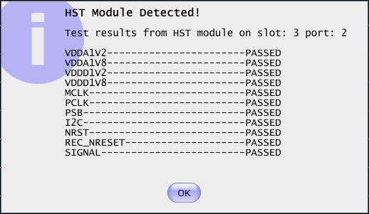
If you have a headstage test module, you can run a suite of tests to ensure the headstage is functioning properly. When the Neuropix plugin is dropped into the signal chain and at least one headstage test module is connected to the PXI system, the GUI will automatically run all headstage tests and output the results in a popup window:
Built-in self tests
If you have a probe that's not working properly, these tests can be used to help pinpoint where the problem lies.
To run each test, select one from the drop-down menu, and click the "RUN" button. After the test completes, the name of the test will be updated to indicated whether it passed or failed.
| Name | Approx. Running Time | Purpose |
|---|---|---|
| Test probe signal | 30 s | Analyzes if the probe performance falls within a specified tolerance range, based on a signal generated by the headstage |
| Test probe noise | 30 s | Calculates probe noise levels when electrode inputs are shorted to ground |
| Test PSB bus | <1 s | Verifies whether signals are transmitted accurately to the headstage |
| Test shift registers | 1 s | Verifies the functionality of the shank and base shift registers |
| Test EEPROM | 1 s | Tests the EEPROM memory storage on the flex, headstage, and BSC |
| Test I2C | <1 s | Verifies the functionality of the I2C memory map |
| Test Serdes | <1 s | Tests the integrity of the serial communication over the probe cable |
| Test Heartbeat | 3 s | Tests whether the heartbeat signal between the headstage and BSC is working properly |
| Test Basestation | <1 s | Tests the BSC board |