Neuropix-3a
- Josh Siegle
IMPORTANT: The Open Ephys GUI documentation has migrated to a new site – please visit https://open-ephys.github.io for the most up-to-date information.
This module is designed to communicate with one Neuropixels "Phase 3a" probes from IMEC (Options 1-4). It's possible to use up to 3 probes per computer by running multiple instances of the Open Ephys GUI (more information below). The source code for this modules can be found in the neuropixels-3a repository.
For information on the Neuropixels PXI data acquisition system for Neuropixels 1.0 probes, please see this page.
Hardware Requirements
- Xilinx KC705 FPGA evaluation board (configured with Neuropixels firmware)
- Gigabit Ethernet card
- Ethernet cable
- Neuropixels Phase 3a basestation card
- Neuropixels Phase 3a cable (white dual coax, Omnetics-to-Omnetics)
- Neuropixels Phase 3a headstage
- Neuropixels Phase 3a probe
Minimum computer specifications
- 4 CPU cores, 2.4 GHz processor frequency
- 16 GB RAM
- 1 TB SSD
- Windows 7 or Windows 10 operating system
Connecting to the hardware
This guide assumes you’ve read IMEC’s Phase IIIA System User Manual and followed the steps required to configure the FPGA. Also be sure to check that your gigabit Ethernet card has its IP address set to 10.2.0.123, or 10.2.X.123 if you're using multiple probes on one computer (see this page for more information).
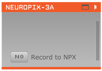
Once your hardware is configured and plugged in, you can drag and drop the Neuropix-3a module from the Processor List type onto the signal chain. It will take a few seconds to connect to the basestation. Once it’s ready, an orange editor will appear. With this simple signal chain (a single processor), you’ll be able to record data, but not visualize it.
Note: If no basestation is connected, the GUI will search for ~20 s, then display a grayed-out processor.
Setting probe parameters
The parameters of the probe are set through a graphical interface. This can be accessed by clicking the “tab” button at the top of the Neuropix processor (to open it in the main GUI window) or the “window” button (to open it in a separate window).
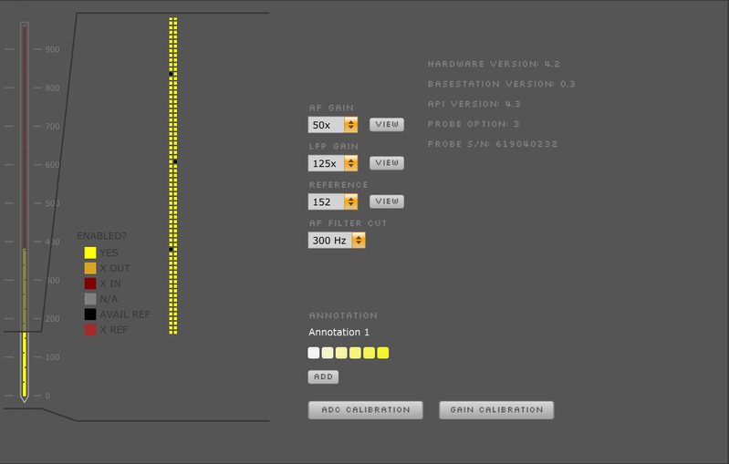
Within this interface, you update the following settings:
- AP Gain (amplifier gain for AP channels, 50x-2500x, default = 500x)
- LFP Gain (amplifier gain for LFP channels, 50x-2500x, default = 250x)
- Reference (External, plus channels 37, 76, 113, 152, 189, 228, 265, 304, 341, or 380, default = External)
- AP Filter Cut (300 Hz, 500 Hz, or 1000 Hz high pass, default = 300 Hz)
For Option 3 and 4 probes, you can select which channels to acquire data from by clicking on those channels and pressing the ENABLE button. For every channel that is enabled (yellow), another channel will be disabled (red).
Probe calibration
You'll have to manually load the probe’s gain calibration settings from the EEPROM. To do this, press the ADC CALIBRATION and GAIN CALIBRATION buttons. This must be done every time the probe is powered on, and can take up to 10 minutes. The GUI will be frozen during this time, so please be patient! You’ll know it’s finished when the button icon changes color.
Visualizing continuous signals
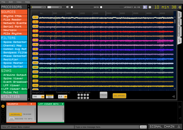
To visualize the data coming off of the probe, drag and drop an LFP Viewer to the right of the Neuropix source module. Open the display by clicking the tab or window button at the top of the processor. Data streaming from the Neuropix module will be visible in the LFP Viewer. To select whether you're viewing the AP band or the LFP band, switch the sub-processor number in the LFP Viewer editor. Unfortunately, this can only be done when acquisition is stopped.
You can change the timebase, input range, channel spacing, or color scheme of the display. Extra options are exposed by clicking the arrow button. We recommend using an input range of 250 uV and a channel spacing (size) of 50 pixels. The "DC OFFSET" button will automatically subtract the constant voltage offset from each channel (for display purposes only).
Acquiring and recording data
To start acquisition, press the “acquire” (play) button in the GUI control panel. It will take a second or two to clear the probe buffer, but after that you should see the signals streaming through the LFP Viewer.
By default, all the data from the source node will be saved, but it’s also possible to save data at every point in the processing pipeline. This is necessary if you’re using the GUI to deliver any type of closed-loop feedback.
Before pressing the record button, open the recording parameters panel by clicking on the arrow at the far right of the control panel. Here, you can select the format and the recording directory. Once you press the record button, data will be saved into a folder with an auto-generated name. You can append or prepend a string to the folder name to specify, for example, your animal ID or experimental protocol.
The default format is the "Binary" format, which writes the data to a flat binary file of int16s in the form "ch1 sample 1, ch2 sample 1, ... ch384 sample 1, ch1 sample2, etc." There are separate files for the AP band (30 kHz) and LFP band (2.5 kHz). Events are saved as numpy arrays. More info on the format can be found here. To convert from the stored int16 values to microvolts, simply multiply by 0.195.
We recommend saving data to a directory on a solid-state drive, to improve disk writing efficiency.
Within the Neuropix processor itself, you can select whether to automatically stream data to an “NPX” binary file. You will be able to save data into a more convenient format using the GUI’s built-in recording functions, but it may be useful to write the raw data packets coming off of the probe for testing purposes. If recording is enabled (YES), a new file named recording#.npx will be written every time data acquisition is started (regardless of whether the GUI is recording data), where # indicates the number of times data acquisition has started since a connection was made to the basestation. These files can be overwritten, so make sure to rename or move them if you want them to be saved permanently.
Saving and loading signal chains
You don’t have to re-build your signal chain every time you use the GUI. To save this signal chain for future use, press Ctrl-S (or use the File drop-down menu). Alternatively, you can select “Reload config on startup” from the File menu, and the GUI will automatically load the signal chain that was open the last time the application was used.
The Neuropix module writes the following information into the settings.xml file (saved each time recording is started)
- probe option and serial number
- probe AP gain, LFP gain, reference channel, and filter cutoff
- basestation version and API version
When loading a previously saved signal chain, the AP gain, LFP gain, reference channel, and filter cutoff will be restored to the previous settings. However, if you have enabled alternate channel configurations for an Option 3 and 4 probe, these are not currently saved or loaded.
Note: Connecting to and configuring the Neuropix probe takes a few seconds, so please be patient when loading saved signal chains that contain a Neuropix source module.