Headstage Channel Mapping
- Jakob Voigts
- Alex Leighton
The channel mapping of a headstage describes the relationship between the connector pin and the headstage channel as it arrives in software. To fully understand which electrode corresponds to which channel in software, you need to combine your headstage mapping with your EIB map. Always make sure that you are using the appropriate configuration, and if in doubt, test the mapping with a EIB by grounding out (you can use a wire to connect this pin to the ground via of the EIB) or injecting signal into one pin at a time and checking if the correct channel in software is affected.
Low-profile SPI headstage (Hirose)
If you are using the low-profile Hirose SPI headstage, bought from Open Ephys Production site, use this sheet to map your tetrodes to your software. It also includes the corresponding Hirose EIB (v.1.2) mapping. Using the classic Open Ephys Acquisition Board, channels will show up in software as if you sorted the sheet by the intan channel number.
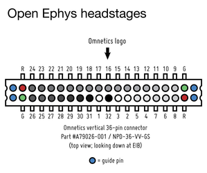
Standard-profile SPI headstage (Omnetics)
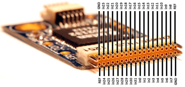
This is the standard headstage that came with the Open Ephys starter kit. It is part number #C3324 from Intan, see their pinout below:
ONIX
All EIB and headstage mapping for ONIX are available here.
Older headstages:
Generally, different headstage designs should not be assumed to follow the same channel mapping. While we'll try to keep the mapping standardized, smaller headstage size or shorter signal paths are usually more important than standardization of the channel mapping.
We'll try to supply appropriate example config files for all designs, if you are missing one, please consider making one and add it as a example config file in the GUI repository.